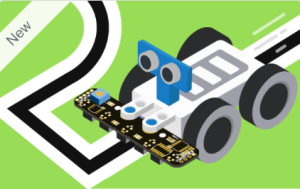

The 5-CH IR Line Sensor Array Extension helps Quarky and Quarky Intellio robots follow predefined paths using five infrared sensors positioned across the front of the robot.
Each sensor detects whether a line is present beneath it. By analysing these readings, the robot can determine whether it is moving straight, drifting towards one side, approaching a junction, or losing the line.
The extension provides functions for:
The same extension supports Quarky and Quarky Intellio, with the initialisation and hardware connection process adapted to the selected board.
A 5-channel IR sensor array consists of five infrared sensors arranged horizontally to detect the position of a line.
The sensors are named according to their physical positions, from left to right.
| Sensor | Position | Function |
| IR-L | Leftmost | Detects a line towards the far left |
| IR-SL | Slightly Left | Detects a line slightly left of centre |
| IR-C | Centre | Detects a line directly beneath the centre |
| IR-SR | Slightly Right | Detects a line slightly right of centre |
| IR-R | Rightmost | Detects a line towards the far right |
When connected to Quarky Intellio, the sensor array communicates through a compatible Mini Expansion Board or Expansion Board.
The selected expansion board provides the I2C interface used to read sensor data and the motor-control interface used to move the robot.
The line-following program reuses the expansion board’s existing I2C object rather than creating a separate I2C bus.
This allows the sensor and motor-control functions to operate through the selected expansion board.
The connection process varies depending on whether you are using Quarky or Quarky Intellio.
Step 1: Connect the 5CH IR Sensor Array
For Quarky
Connect the sensor array directly to the Quarky board using the I2C connections.
| 5CH IR Sensor Array | Quarky |
| D1 | D1 (SDA) |
| D2 | D2 (SCL) |
The sensor communicates through Quarky’s configured I2C pins.
For Quarky Intellio
Connect the sensor array to the selected Mini Expansion Board or Expansion Board.
| 5CH IR Sensor Array | Mini Expansion / Expansion Board |
| D1 | SCL |
| D2 | SDA |
Next, connect the Intellio main board to the expansion board.
| Quarky Intellio Pin | Expansion Board Pin |
| A1 / D1 | D1 |
| A2 / D2 | D2 |
This creates a communication path between Intellio, the expansion board, and the sensor array.
Important: The supplied wiring references use different D1/D2 signal-label conventions for Quarky and the expansion-board arrangement. Verify the SDA/SCL labels on the actual hardware before making connections. The tables above preserve the board-specific mappings supplied for this extension.
Step 2: Connect the Motors and Power Supply
For Quarky
For Quarky Intellio
Step 3: Verify the Connections
Before switching on the robot:
Important: Disconnect the power supply before modifying the wiring.
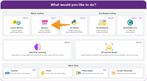
Step 1: Open PictoBlox and select the Block Coding environment.
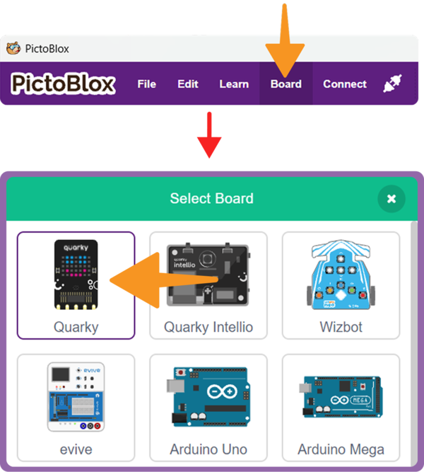
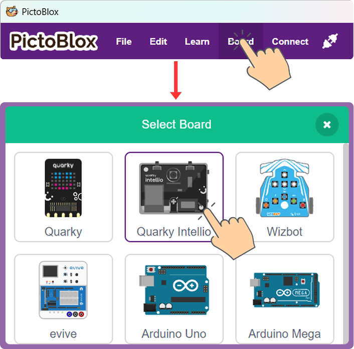
Step 2: Open the Board menu and select either Quarky or Quarky Intellio, depending on your hardware.
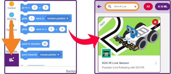
Step 3: Click the Add Extension button at the bottom-left corner of the Blocks Palette.
Step 4: Search for and select 5-CH IR Line Sensor Array.
Step 5: Open the 5-CH IR Line Sensor Array category from the Blocks Palette.
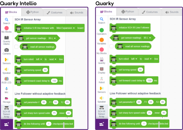
The extension provides blocks for sensor readings, motor speed configuration, junction navigation, standard line following, and PID-based line following.
Note: The extension uses board-specific initialisation blocks. The remaining line-following blocks provide common functionality for Quarky and Quarky Intellio.
The following table summarises the Python functions associated with the extension blocks.
| Block | Quarky Python | Quarky Intellio Python |
| Initialise Line Follower | LineFollower5IR(scl_pin=19, sda_pin=18) | LineFollower5IR(i2c=mini.i2c, motor_driver=mini) or Expansion equivalent |
| Get Sensor Readings | getirstate() | getirstate() |
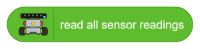
| Read All Sensor Readings | getallsensorreadings() | getallsensorreadings() |
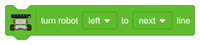
| Turn Robot | turnrobot5ir() | turnrobotusingir() |
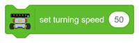
| Set Turning Speed | setturningspeed() | setturningspeed() |
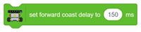
| Set Forward Coast Delay | setturningforwarddelay() | setturningforwarddelay() |
| Set Line Following Parameters | setlinefollowerparameter5ir() | setlinefollowerparameter5ir() |
| Set Sharp Turn Speed | setSharpTurnParameter5IR() | setSharpTurnParameter5IR() |
| Standard Line Following | followlineuntilcheckpoint() | followlineuntilcheckpoint() |
| Set PID Constants | setpidconstants() | setpidconstants() |
| Set PID Speed Parameters | setpidspeedparameter5ir() | setpidspeedparameter5ir() |
| PID Line Following | followlinepiduntilcheckpoint() | followlinepiduntilcheckpoint() |