

The Advanced Line Following Extension gives you two distinct methods for navigating a line-following arena with Quarky:
With Adaptive Feedback (PID): Uses Proportional-Integral-Derivative control for precise, responsive navigation. Ideal for complex arenas and competition-grade performance.
Without Adaptive Feedback: Straightforward motor-speed control without PID. Best for simple arenas or as a starting point before tuning PID parameters.
The extension features the following sections:
Please make sure to use PictoBlox version 9.1.0 or later for Quarky’s latest Extension support. Click Download PictoBlox to visit the download page, select your operating system, and follow the on-screen instructions to install the latest version.
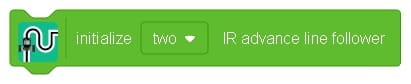
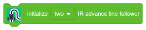
Sets up the advanced line following system once the circuits are connected to Quarky. Always use this block first, before any other line that follows it.
Block:
Python:
from quarkyAdvanceLineFollowing import AdvanceLineFollowing
linefollow = AdvanceLineFollowing(IR_NUM = 2)
The two supported IR sensor configurations are:
Two External IR Sensors connected (via Analog Pins) to the Quarky Expansion Board
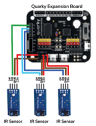
Three External IR Sensors connected (via Digital Pins) to the Quarky Expansion Board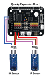
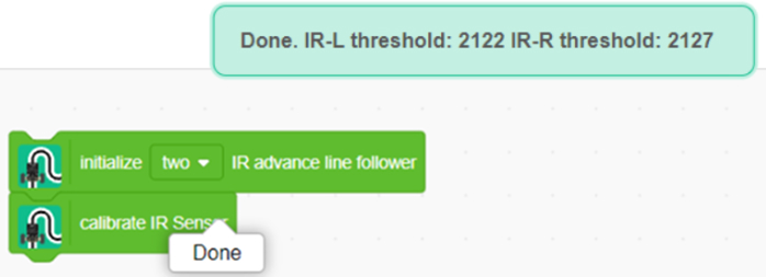
The robot moves forward and reverse for a specific duration while collecting sample data from the IR sensors on both white and black surfaces. Run this once before starting line following.
Block:
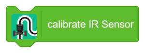
Calibrating Quarky’s internal (built-in) IR sensors:
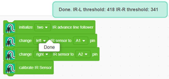
Calibrating external IR sensors (Pins A1, A2, or A3):
Follow this exact block order:
Note: Failing to follow this exact sequence will cause the system to display calibration values for the internal sensors instead of the connected external ones.
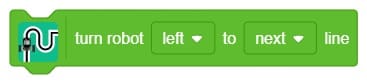
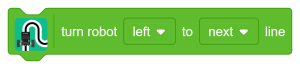
Turns the robot left or right at a junction, continuing movement until the next black line is detected.
Block:
Python:
turnrobotusingir(‘left’,’next’)
Note: You need to set the IR threshold to adjust the robot’s turning behaviour correctly.
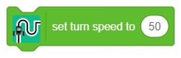
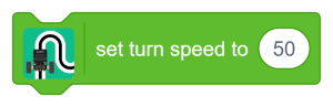
Sets the motor speed (voltage supplied to the motors) used during junction turns.
Block:
Python:
setturingspeed(50)
Note: High-speed motors operate only at higher voltages and may not respond to lower speed values.
Controls the LED feedback feature of the line follower sensor, enabling or disabling it.
Block:
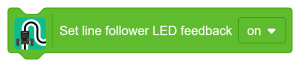
Python:
linefollow.setLedFeedback(“on”)
Controls the robot’s forward coasting duration (in milliseconds) after detecting a line terminal during a junction turn. The coast delay determines how long the robot continues to move freely after the line terminal is detected. Optimising this value achieves smoother, more precise movement and better control over the stopping distance.
Block:
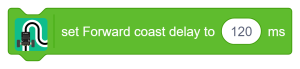
Python:
linefollow.setturningforwarddelay(120)
Note: This block can be used together with the “Turn the robot on a junction” block for best results.
Note: Two IR sensor line following works with analog values only. For external sensors, ensure the analog output is connected to the analog pins of Quarky (refer to Section 1.1).
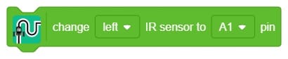
Set which two IR sensors to use for line following for left and right sensing, respectively. Select between the onboard Quarky IR sensors (IR-L or IR-R) or external IR sensors by selecting the analog pin to which they are connected.
Block:
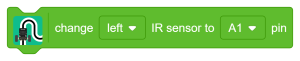
Python:
setlinefollowerparameter(‘left’,’A1′)
| Parameter | Options | Description |
| Side | left, right | Which sensor position to configure |
| Pin | IR-L, IR-R, A1, A2, A3 | Onboard sensors or an external analog pin |
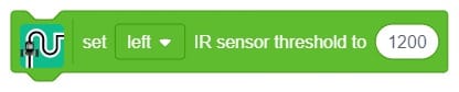
Sets the IR threshold for the onboard or external IR sensor connected to an analog pin of Quarky. Use the “read analog pin” block to get actual sensor values from your arena before setting this.
Block:
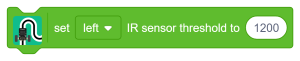
Python:
setirthreshold(‘left’,1200)
Note: Three IR sensor line following works with digital values only. The threshold is set by the potentiometers on the sensors as they work with digital values.
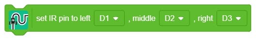
Sets the three pins to which the IR sensors are connected for line following — for left, middle, and right sensing, respectively.
Block:
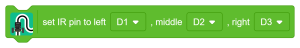
Python:
setirsensor(“D1″,”D2″,”D3”)
This section contains blocks and Python functions for regular line following without adaptive feedback.
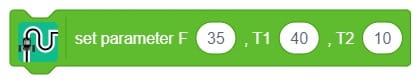
The parameters in this block are the same as the regular line following blocks in the Robot Extension of the Quarky board. They define the speeds of motors in different scenarios while following the black line on a white path.
Block:
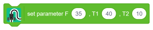
Python:
setlinefollowerparameter(35,40,10)
| Parameter | Description |
| F | The speed at which the robot moves forward when both sensors detect white |
| T1 | The speed of the forward-moving motor is set to turn the robot along the black line gently |
| T2 | Speed of the reverse-moving motor to turn the robot along the black line gently |
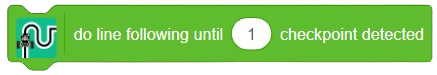
The robot performs line following until the specified number of junctions or checkpoints on the line-following arena are detected — that is, until it detects black on both IR sensors simultaneously.
Block:
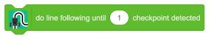
Python:
dolinefollowinguntilcrossinglinesdetect()
Note: This block will not work correctly if the robot starts positioned on a junction, as both IR sensors already detect black, and the stop condition triggers immediately.
This section contains blocks and Python functions that use adaptive feedback (based on a PID filter) for line following.
Sets the three PID constants Proportional, Integral, and Derivative — that are used to improve feedback from the IR sensors and refine the robot’s movement.
Block:
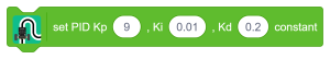
Python:
setPIDconstantparameter(0.8,0.01,0.2)
Proportional (Kp) This component enables the robot to make immediate, precise adjustments based on its distance from the line. If the robot drifts too far to the right, it steers left, and if it veers too far to the left, it steers right to correct its course.
Integral (Ki) The integral component monitors how long the robot has been off the line. If the deviation persists for an extended time, this part applies a larger correction to bring the robot back on track more effectively.
Derivative (Kd) The derivative component anticipates future errors by analysing the rate at which the robot drifts from the line. This ensures smooth, predictive adjustments, helping to prevent overshooting and maintain stability.
The control output formula is:
Control Output = Proportional + Integral + Derivative
So, the PID controller combines these three components to continuously adjust the robot’s movements, keeping it as close to the line as possible while moving smoothly and fast. Think of it as a smart system that balances and corrects itself as it moves, ensuring it follows the line accurately. PID line followers are commonly used in robotics competitions and educational settings to teach about control systems and automation.
Note: For three IR sensor configurations, use Kp ≥ 7 for better results.
In Quarky’s “Do Line Following” block, the system uses two infrared (IR) sensors — one on the left and one on the right — to navigate along a line.
Sample analog values registered by the sensors:
| Condition | Left Sensor | Right Sensor |
| On white surface | 150 | 170 |
| On black line | 820 | 750 |
| Robot drifted right | 820 (black) | 170 (white) |
When the robot drifts right, the left sensor moves onto the black line while the right remains on white. The error is calculated as:
Error = (Left Sensor Value − Right Sensor Value) / 10
= (820 − 170) / 10
= 65
Proportional Only (Kp = 0.5, Ki = 0, Kd = 0)
Proportional = Kp × Error
= 0.5 × 65
= 32 (approximately)
Control Output = 32 + 0 + 0 = 32
Assuming base speed = 40, minimum speed = 0, maximum speed = 80:
Left Motor Speed = Base Speed − Control Output = 40 − 32 = 8
Right Motor Speed = Base Speed + Control Output = 40 + 32 = 72
Proportional and Integral Only (Kp = 0.5, Ki = 0.01, Kd = 0)
Consider a scenario where the robot is stuck, and the tyres are slipping due to excessive weight and a low battery. The integral term accumulates error over time to apply a growing correction.
Iteration 1:
I = I + Error = 0 + 65 = 65
Control Output = (0.5 × 65) + (0.01 × 65) + 0 = 32.65
Left Motor Speed = 7.35
Right Motor Speed = 72.65
Iteration 2:
I = 65 + 65 = 130
Control Output = (0.5 × 65) + (0.01 × 130) + 0 = 33.3
Left Motor Speed = 6.7
Right Motor Speed = 73.3
Proportional, Integral, and Derivative (Kp = 0.5, Ki = 0.01, Kd = 0.2)
In a small arena requiring a significant turn or U-turn, increasing Kp alone may cause excessive oscillations.
If the error increases to 76:
D = Previous Error − Current Error = 65 − 76 = −11
Control Output = (0.5 × 76) + (0.01 × 76) + (0.2 × −11)
= 38 + 0.76 − 2.2
= 36.56
Left Motor Speed = 3.44
Right Motor Speed = 76.56
In the next loop, with a new error of 43:
I = 76 + 43 = 109
D = 76 − 43 = 33
Control Output = (0.5 × 43) + (0.01 × 10⁹) + (0.2 × 33)
= 21.5 + 1.09 + 6.6
= 29.19
Left Motor Speed = 10.81
Right Motor Speed = 69.19
This iterative process continues, with the derivative term helping to manage the robot’s response to changing errors and ultimately enhancing its stability.
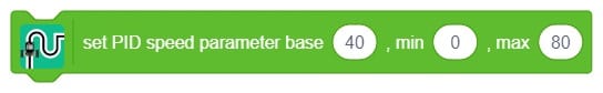
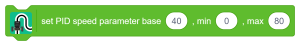
Defines the motor speed range used during PID-controlled line following.
Block:
Python:
setPIDspeedparameter(40,0,80)
| Parameter | Description |
| Base Speed | The speed during line following |
| Min Speed | The minimum motor speed when the robot is turning |
| Max Speed | The maximum motor speed when the robot turns, and the black line is detected |
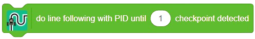
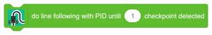
Initiates line following using the PID algorithm and stops the robot when the specified number of crossing lines or checkpoints is detected. You must set the IR threshold to stop the robot at the crossing lines. To start line following, both PID speed and constant parameters must be set first.
Block:
Python:
dolinefollowingwithPID()
Notes:
The extension helps you to speed up your quarky in the line following using blocks and Python functions.