The project demonstrates how to create a smart plug that can be controlled by an IoT device and that can retrieve information from the cloud. The smart plug can be used to turn lights ON and OFF.
Creating a Switch on Adafruit IO
We will be using Adafruit IO for creating a switch on the cloud. Follow the instructions:
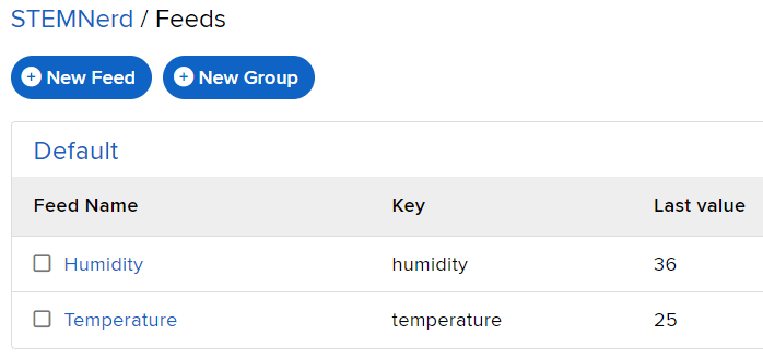
- Create a new Feed named Light.
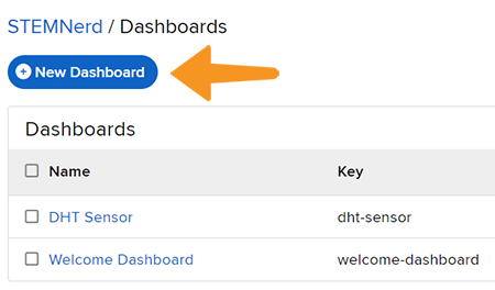
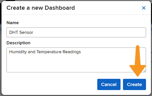
- Create a new Dashboard named Light Control.
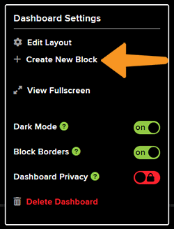
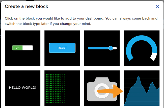
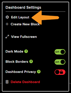
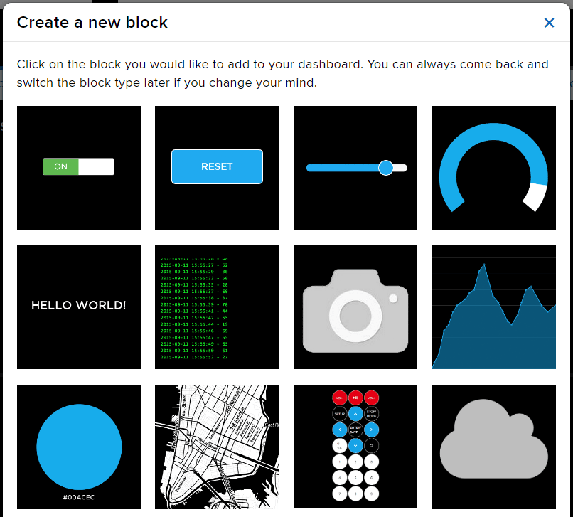
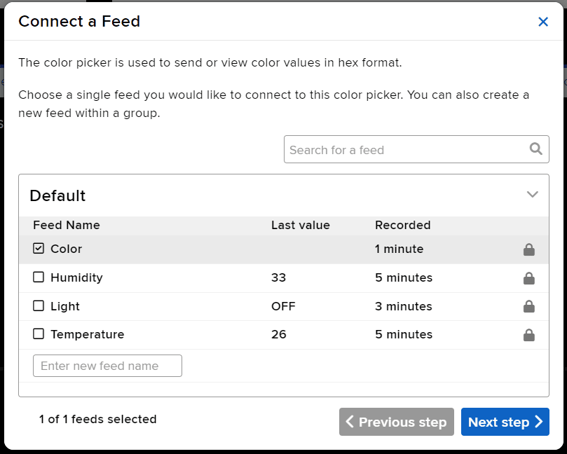
- Edit the Dashboard and add a Toggle Block.
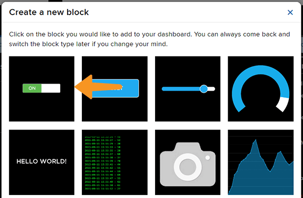
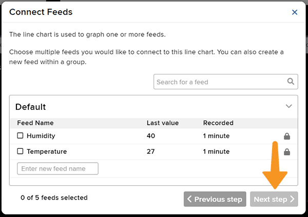
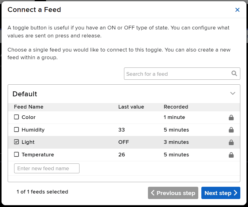
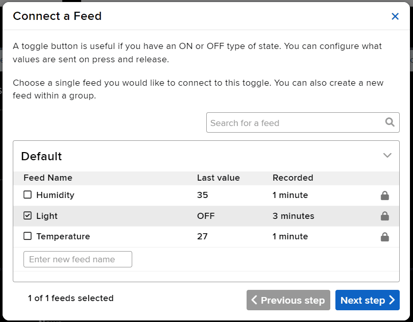
- Connect the Light feed to the block and click on Next Step.
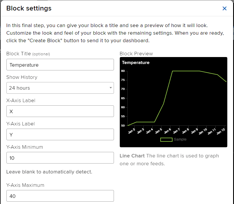
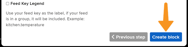
- Edit the Block Setting and click on Create Block.
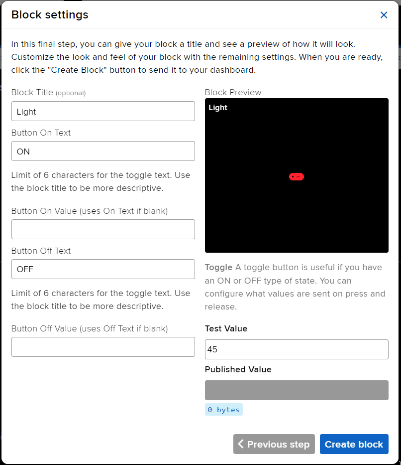
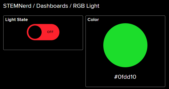
- Block is added. You can try to toggle the switch.
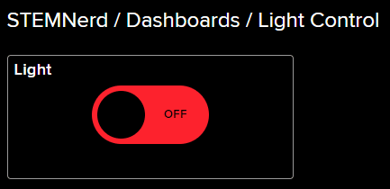
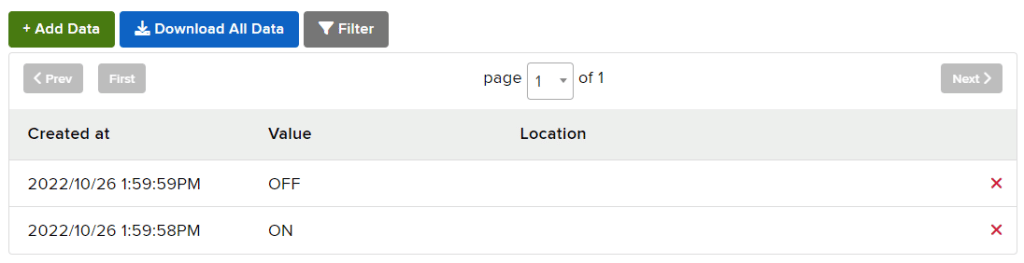
- Go to the Light feed. You will observe the value of the feed changing as we click on the switch on the Dashboard.
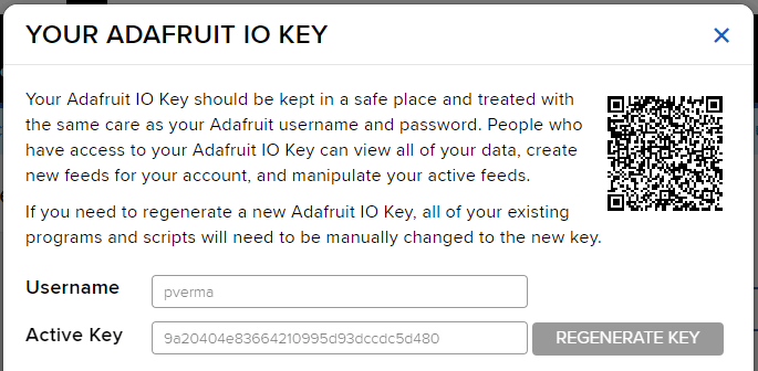
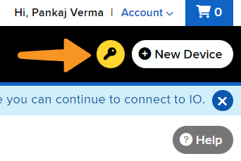
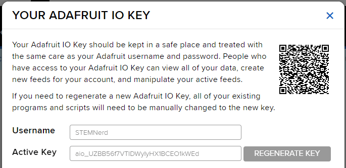
Adafruit IO Key
You can find the information about your account once you log in from here:
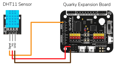
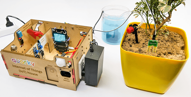
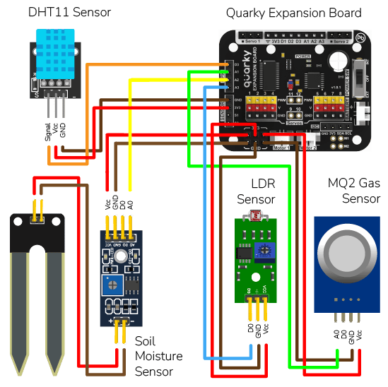
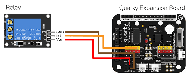
Circuit For the Lamp
The bulb is connected to the smart plug which is controlled with a relay.
Note: A relay is an electromechanical switch that is used to turn on or turn off a circuit by using a small amount of power to operate an electromagnet to open or close a switch.
If the relay is ON, the smart switch gets ON, turning on the light. The relay has the following connections:
- GND Pin connected to GND of the Quarky Expansion Board.
- VCC Pin connected to VCC of the Quarky Expansion Board.
- Signal Pin connected to Servo 4 of the Quarky Expansion Board.
Python Code for Stage Mode
This Python code connects to Adafruit IO using the given credentials and checks if the light is ON or OFF. If the light is ON, then the code sets the relay to 0 (ON) and sets the LED to white with a brightness of 100. If the light is OFF, then the code sets the relay to 1 (OFF) and sets the LED to black with a brightness of 100. The code runs in an infinite loop to continuously check the status of the light.
#This code is used to control the light in an IOT house.
#The code connects to Adafruit IO using the given credentials and checks if the light is "ON" or "OFF".
#If the light is "ON" then the code sets the relay to 0 (ON) and sets the LED to white with a brightness of 100.
#If the light is "OFF" then the code sets the relay to 1 (OFF) and sets the LED to black with a brightness of 100.

quarky = Quarky() #Creating an object for the Quarky class

adaio = AdaIO() #Creating an object for the AdaIO class
house = IoTHouse() #Creating an object for the IoTHouse class

adaio.connecttoadafruitio("STEMNerd", "aio_UZBB56f7VTIDWyIyHX1BCEO1kWEd") # Connecting to Adafruit IO using the given credentials

while True: # Loop that runs forever
  if (adaio.getdata("Light") == "ON"): #Checking if the light is "ON"
    house.setrelay(0, "pwm4") # Setting the relay to 0
    quarky.setled(1, 1, [255, 255, 255], 100) #Setting the LED to white with a brightness of 100

  if (adaio.getdata("Light") == "OFF"): #Checking if the light is "OFF"
    house.setrelay(1, "pwm4") # Setting the relay to 1
    quarky.setled(1, 1, [0, 0, 0], 100) #Setting the LED to black with a brightness of 100
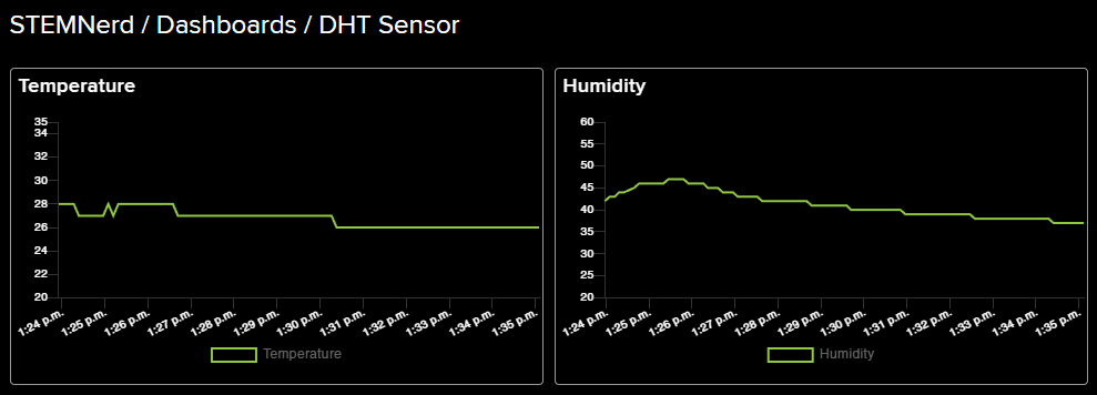
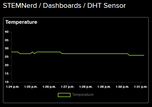
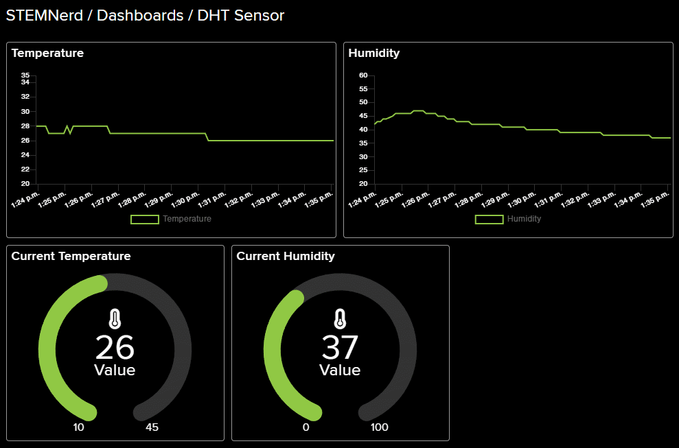
Output
IoT-Enabled Smart Plug Upload Mode
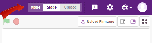
You can also make the IoT Enabled Smart Plug work independently of PictoBlox using the Upload Mode. For that switch to upload mode and replace the when green flag clicked block with when Quarky starts up the block.
This code connects to a wifi network and an Adafruit IO account, creates an object for the IoTHouse class, and then sets a relay and LED based on the data from the Adafruit IO account. The loop runs forever and will always check if the wifi is connected and if the light is “ON“ or “OFF“. If the wifi is not connected, it will set the LED to red.
from quarky import *

# Connect to a wifi network
import iot
import iothouse
wifi = iot.wifi()
wifi.connecttowifi("IoT", "12345678")

# Connect to an adafruit IO account
adaio = iot.AdaIO()
adaio.connecttoadafruitio("STEMNerd", "aio_UZBB56f7VTIDWyIyHX1BCEO1kWEd")

#Creating an object for the IoTHouse class
house = iothouse.iothouse()

while True:  # Loop that runs forever
  # Check if the wifi is connected
  if wifi.iswificonnected():
    if (adaio.getdata("Light") == "ON"):  #Checking if the light is "ON"
      house.setrelay(0, "pwm4")  # Setting the relay to 0
      quarky.setled(1, 1, [255, 255, 255], 100)  #Setting the LED to white with a brightness of 100

    if (adaio.getdata("Light") == "OFF"):  #Checking if the light is "OFF"
      house.setrelay(1, "pwm4")  # Setting the relay to 1
      quarky.setled(1, 1, [0, 0, 0], 100)  #Setting the LED to black with a brightness of 100

  else:
    # Set LED 1 to red
    quarky.setled(1, 1, [255, 0, 0], 100)