Table of Contents

adaio.connecttoadafruitio()

Function Definition: adaio.connecttoadafruitio(username = "username", AIO Key = "AIO key")

Parameters

NameTypeDescriptionExpected ValuesDefault Value
usernamestringThe username of the Adafruit IO account.String"username"
AIO KeystringThe key of the Adafruit IO account.String"AIO key"

Description

The function creates an Adafruit IO object that set up the API connection between the PictoBlox and the Adafruit server with the specified username and AIO key.

adaio = AdaIO()

adaio.connecttoadafruitio("username","AIO key")

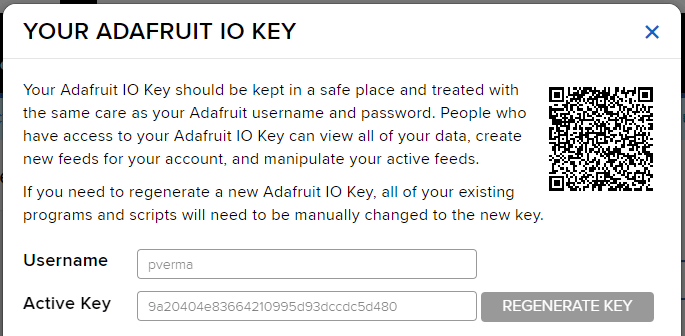
You can find the information about your account once you log in from here:

Note: Make sure you are login on Adafruit IO: https://io.adafruit.com/

Example

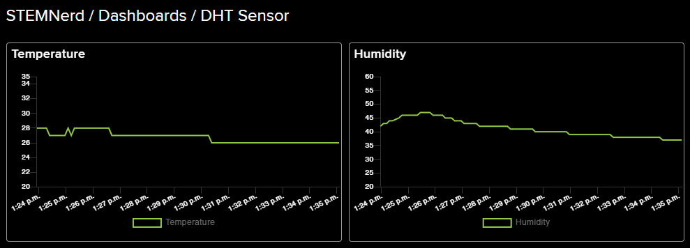
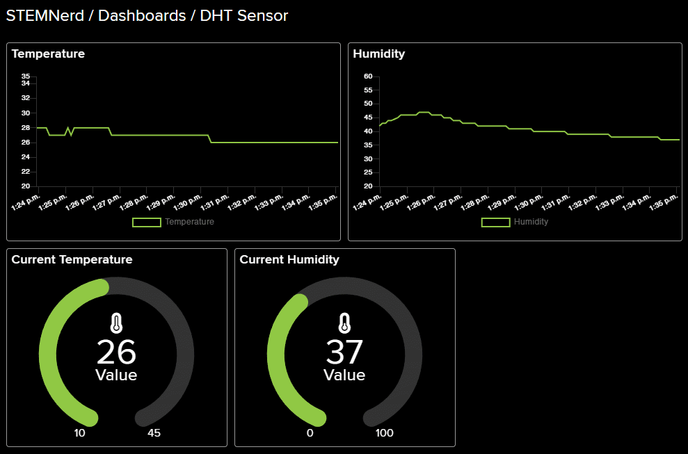
Learn how to connect a DHT sensor to PictoBlox and use the Adafruit IO cloud service to send temperature and humidity data to the cloud. Create a dashboard to visualize the temperature and humidity data with the help of line chart and gauge elements.

We will use the Adafruit IO cloud service to send data from a humidity and temperature sensor to the cloud in the Python Coding Environment of PictoBlox. Adafruit IO is a cloud service that allows you to send data from sensors and other devices to the cloud, where it can be stored and analyzed.

Adafruit IO Key

You can find the information about your account once you log in from here:

Note: Make sure you are login on Adafruit IO: https://io.adafruit.com/

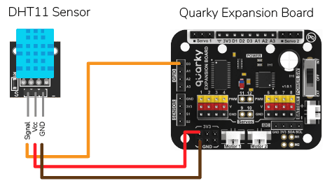
DHT Sensor Connection to Quarky

DHT sensors have 3 pins: GND, VCC, and Signal. You have to connect the following 3 pins to the Quarky Expansion Board:

  1. GND to Ground Pin of Quarky Expansion Board
  2. VCC to 3.3V or VCC Pin of Quarky Expansion Board
  3. Signal to the D3 (Digital Pin) of the Quarky Expansion Board

Code for Stage Mode

# This code is used to connect to the internet and measure the temperature and humidity of the house.
# First, the Quarky object  are created.
quarky = Quarky()

# Time module is imported.
import time

# AdaIO object is created.
adaio = AdaIO()

# IoTHouse object is created.
house = IoTHouse()

# Then, the connection to Adafruit IO is made.
adaio.connecttoadafruitio("STEMNerd", "aio_UZBB56f7VTIDWyIyHX1BCEO1kWEd")

# The feeds for temperature and humidity are created.
adaio.createfeed("Temperature")
adaio.createfeed("Humidity")

# A while loop is used to measure the temperature and humidity continously.
while True:
  # Temperature is measured using the dhtmeasure function.
  adaio.createdata("Temperature", house.dhtmeasure(1, "D3"))
  # The loop pauses for 1 second.
  time.sleep(1)

  # Humidity is measured using the dhtmeasure function.
  adaio.createdata("Humidity", house.dhtmeasure(2, "D3"))
  # The loop pauses for 5 seconds.
  time.sleep(5)


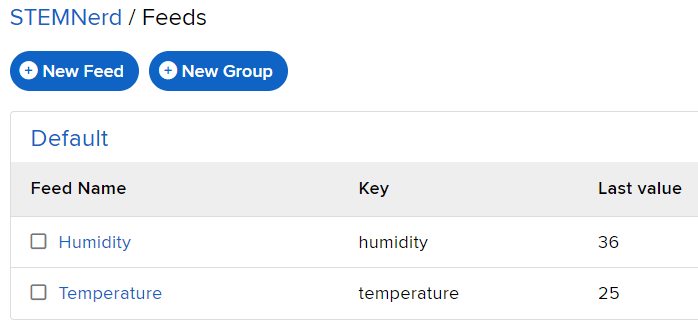
The following feeds are created:

Creating Dashboard

Follow the steps:

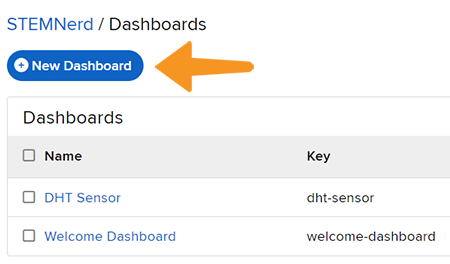
  1. Go to the dashboard and click on New Dashboard.
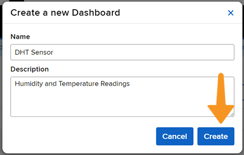
  2. Add the Dashboard Name and Description and click on Create.
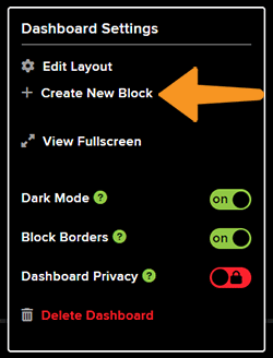
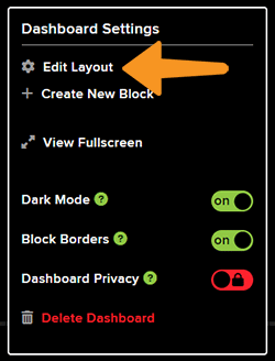
  3. Open the New Dashboard. Click on the Setting icon in the top right corner and then click on Create New Block.
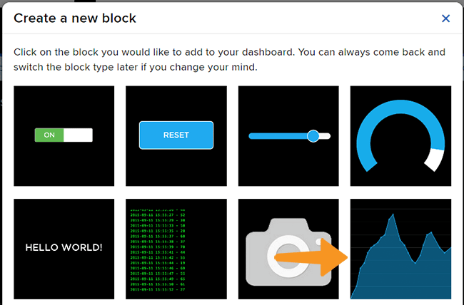
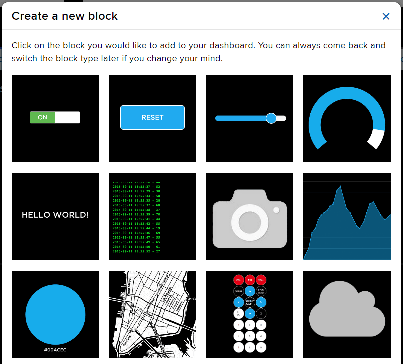
  4. From the options, click on the line chart.
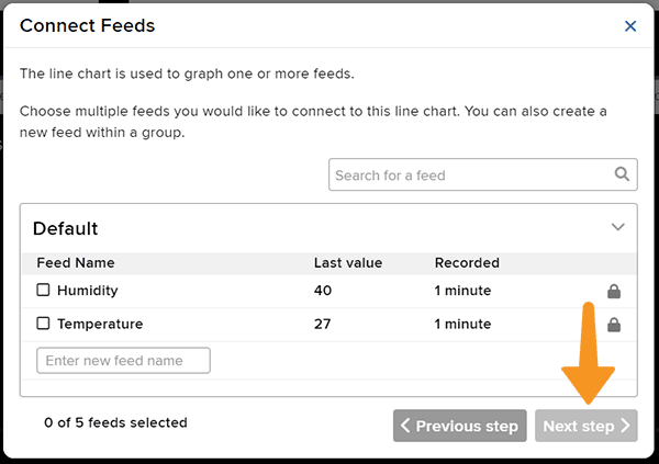
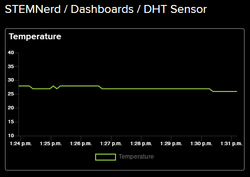
  5. Select the Temperature Feed and click on Next Step.
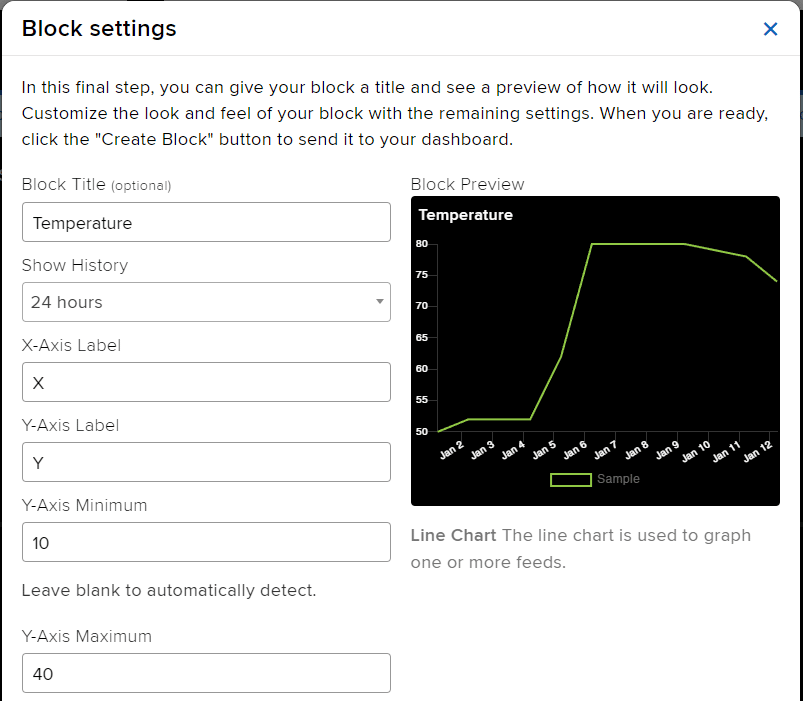
  6. Add the Block Title and the Y-Axis Minimum – Maximum value. Click on Create Block.
  7. You will find the block added on the dashboard.
  8. Add a Humidity block as well. Also, add two gauge elements showing the current temperature and humidity value.
  9. Click on the Setting button and Edit Layout to align all the buttons.
Read More
Learn how to create a light switch in Adafruit IO with Python code. Step-by-step guide on how to connect Quarky to Adafruit IO and create a dashboard with a toggle block.

In this example, we are going to understand how to make a feed on Adafruit IO. Later we will write the Python code that will retrieve the information from the cloud and make the Quarky lights ON and OFF.

Adafruit IO Key

You can find the information about your account once you log in from here:

Note: Make sure you are login on Adafruit IO: https://io.adafruit.com/

Creating a Light Switch in Adafruit IO

  1. Create a new Feed named Light.
  2. Create a new Dashboard named Light Control.
  3. Edit the Dashboard and add a Toggle Block.
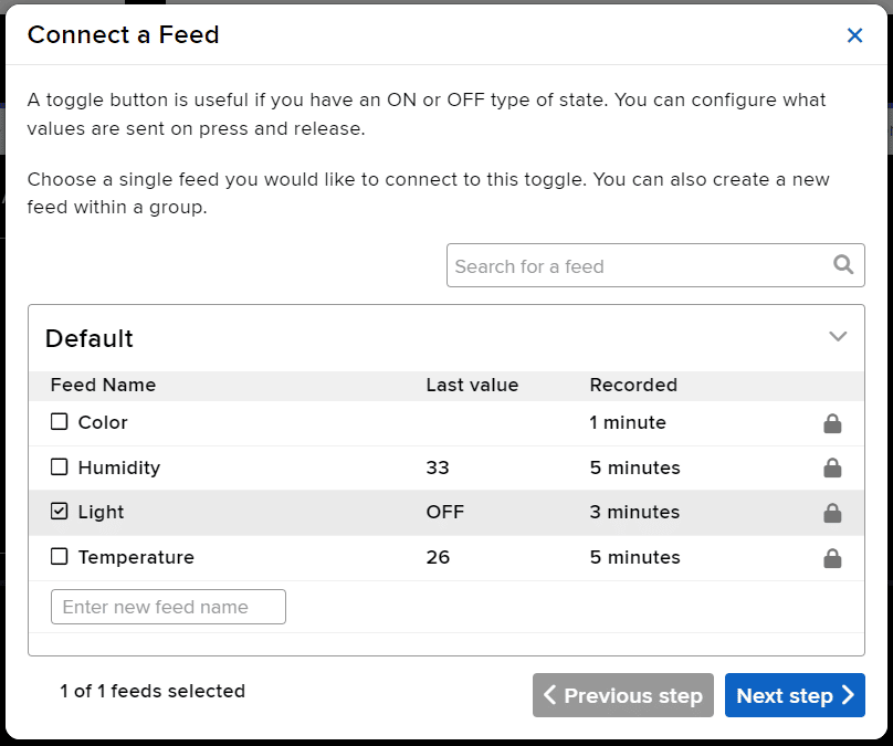
  4. Connect the Light feed to the block and click on Next Step.
  5. Edit the Block Setting and click on Create Block.
  6. Block is added. You can try to toggle the switch.
  7. Go to the Light feed. You will observe the value of the feed changing as we click on the switch on the Dashboard.

Python Code for Stage Mode

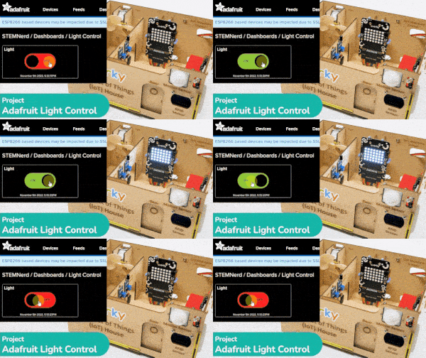
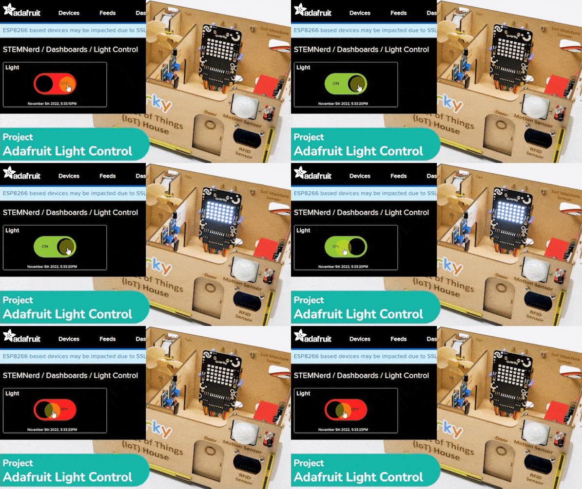
This Python code creates two instances, one of the Quarky class and one of the AdaIO class. It sets the brightness of the Quarky instance to 10 and connects to Adafruit IO using the specified username and key. It then creates a loop that checks to see if the value of theLight feed from Adafruit IO isON“. If the data is “ON” then the white light is turned on on the display, otherwise, the display is cleared.

# Create a new instance of the Quarky class and call it quarky
quarky = Quarky()

# Create a new instance of the AdaIO class and call it adaio
adaio = AdaIO()

# Set the brightness of Quarky to 10
quarky.setbrightness(10)

# Connect to Adafruit IO using the specified username and key
adaio.connecttoadafruitio("STEMNerd", "aio_UZBB56f7VTIDWyIyHX1BCEO1kWEd")

# Create an loop
while True:

  # Check to see if the value of the "Light" feed from Adafruit IO is "ON"
  if (adaio.getdata("Light") == "ON"):
    # If the data is "ON" draw the specified pattern
    quarky.drawpattern("aaaaaaaaaaaaaaaaaaaaaaaaaaaaaaaaaaa")

  # Otherwise, clear the display
  else:
    quarky.cleardisplay()

Output

Python Code for Upload Mode

You can also make the script work independently of PictoBlox using the Upload Mode. For that switch to upload mode.

Note:  In the upload mode your Quarky needs to connect to the WiFi network. You can learn how to do it here: https://ai.thestempedia.com/example/wi-fi-connect-for-quarky-in-upload-mode-python/
# This code connects to a wifi network and an adafruit IO account.
# It also uses the module "quarky" to set the brightness and draw a pattern.
# The code will check if the wifi is connected and if the value of "Light" in the adafruit IO account is "ON",
# it will draw a pattern on the display. If not, it will clear the display.
# If the wifi is not connected, it will set LED 1 to red.

from quarky import *

# imported module
import iot

# Connect to a wifi network
wifi = iot.wifi()
wifi.connecttowifi("IoT", "12345678")

# Connect to an adafruit IO account
adaio = iot.AdaIO()
adaio.connecttoadafruitio("STEMNerd", "aio_UZBB56f7VTIDWyIyHX1BCEO1kWEd")

# Set the brightness
quarky.setbrightness(10)

while True:
  # Check if the wifi is connected
  if wifi.iswificonnected():
    # Check if the value of "Light" in the adafruit IO account is "ON"
    if (adaio.getdata("Light") == "ON"):
      # Draw a while LED pattern on the display
      quarky.drawpattern("aaaaaaaaaaaaaaaaaaaaaaaaaaaaaaaaaaa")
    else:
      # Clear the display
      quarky.cleardisplay()
  else:
    # Set LED 1 to red
    quarky.setled(1, 1, [255, 0, 0], 100)

Troubleshooting:

  1. If the Green Light comes, your Wi-Fi is connected.
  2. If the Red Light comes, your Wi-Fi is not connected. Change the Wi-Fi and the password and try again.
  3. If the Red Cross sign comes, Quarky, Python error has occurred. Check the serial monitor and try to reset the Quarky.
Read More
Learn how to create a Color Switch on Adafruit IO and the Python code needed to retrieve the color information from the cloud and make the Quarky lights ON and OFF with the selected color.

In this example, we are going to make a colored switch in Adafruit IO. Then we will make Python code for Quarky that will retrieve the color information from the cloud and make the Quarky lights ON and OFF with the selected color on the cloud.

Adafruit IO Key

You can find the information about your account once you log in from here:


Note: Make sure you are login on Adafruit IO: https://io.adafruit.com/

Creating the Dashboard for the Color Switch

  1. Create two new Feeds named Light and Color.
  2. Create a new Dashboard named RGB Light.
  3. Edit the Dashboard and add a Toggle Block.
  4. Connect the Light feed to the block and click on Next Step.
  5. Edit the Block Setting and click on Create Block.
  6. Block is added. You can try to toggle the switch.
  7. Next, create another block. This time select Color Picker.
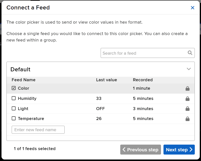
  8. Connect to Color Feed.
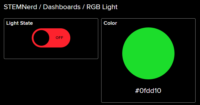
  9. You will find the blocks on the Dashboard. Edit the layout as per your liking.

Python Code for Stage Mode

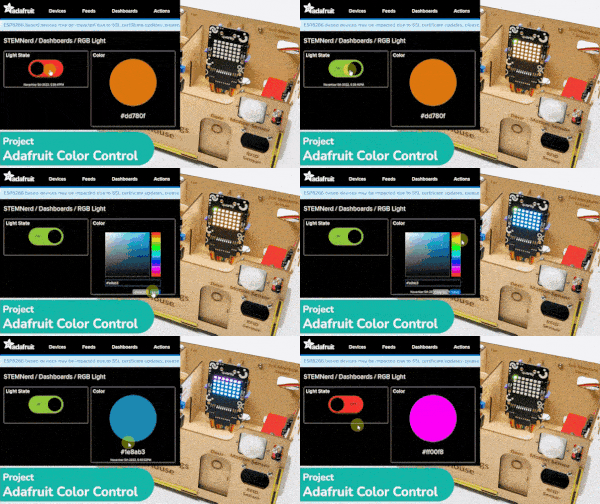
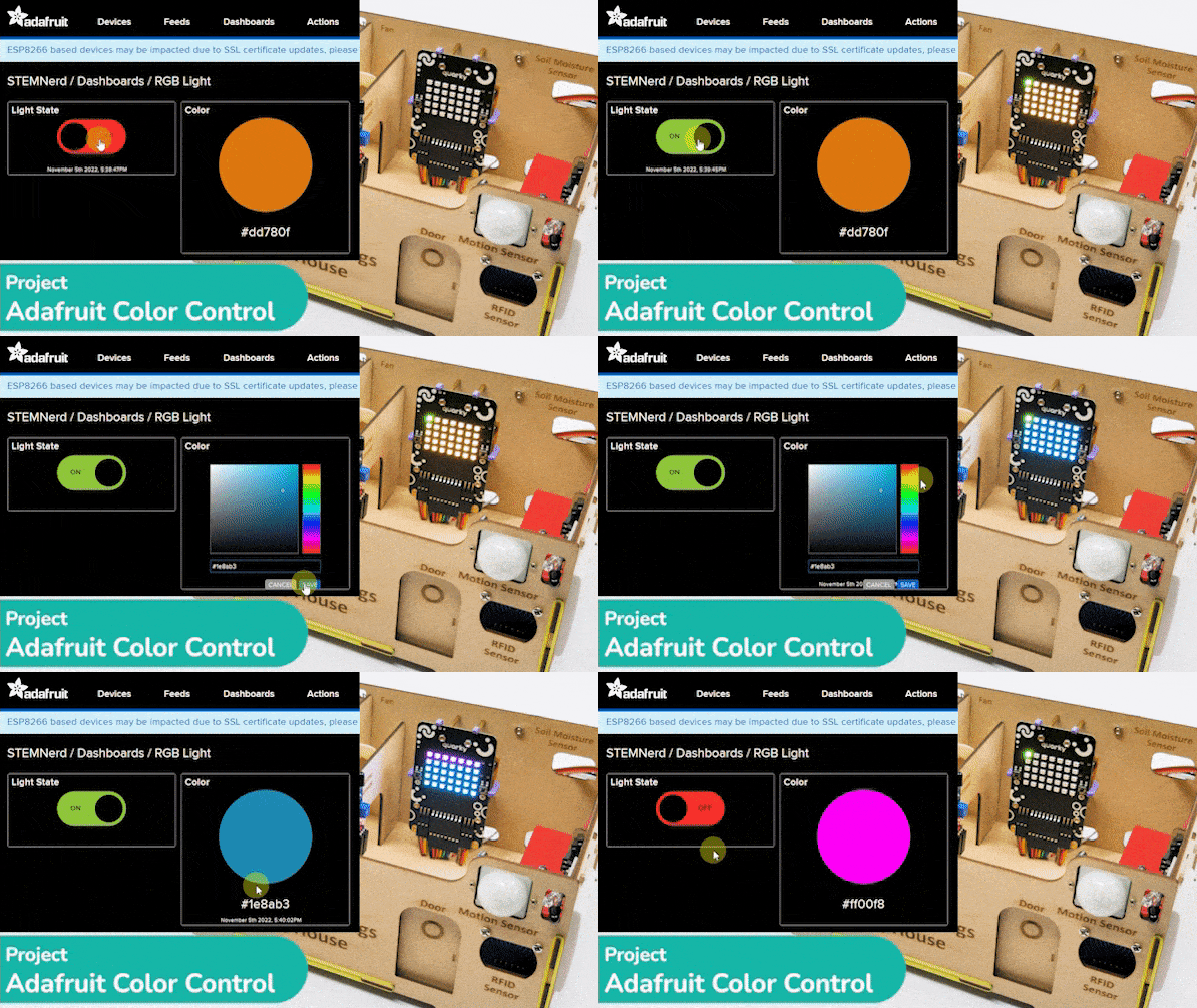
This code creates an instance of the Quarky and AdaIO classes and connects to Adafruit IO using credentials. It then creates a loop that checks if the light is on and, if so, sets the LED on the Quarky to the color from the Adafruit IO data. If the light is not on, the display on the Quarky is cleared. The loop pauses for 1 second before repeating.

# Create an instance of the quarky class
quarky = Quarky()

# Import the time library
import time

# Create an instance of the AdaIO class
adaio = AdaIO()

# Clear the display on the quarky
quarky.cleardisplay()

# Connect to Adafruit IO using the given credentials
adaio.connecttoadafruitio("STEMNerd", "aio_UZBB56f7VTIDWyIyHX1BCEO1kWEd")

# Loop forever
while True:
  # Get the data from Adafruit IO to see if the light is on
  if (adaio.getdata("Light") == "ON"):
    # Get the color data from Adafruit IO
    adaio.getcolordata("Color")
    # Get the RGB values from the color data
    Color = [adaio.getRGB(1), adaio.getRGB(2), adaio.getRGB(3)]
    
    # Loop through the 5 rows and 7 columns on the quarky
    for i in range(1, 6):
      for j in range(1, 8):
        # Set the LED on the quarky to the Color with a brightness of 20
        quarky.setled(j, i, Color, 20)

  # If the light is not on, clear the display on the quarky
  else:
    quarky.cleardisplay()

  # Pause the program for 1 second
  time.sleep(1)


Output

Python Code for Upload Mode

You can also make the script work independently of PictoBlox using the Upload Mode. For that switch to upload mode.

Note:  In the upload mode your Quarky needs to connect to the WiFi network. You can learn how to do it here: https://ai.thestempedia.com/example/wi-fi-connect-for-quarky-in-upload-mode-python/
# Create an instance of the quarky class
from quarky import *

# Import the library
import time
import iot

# Connect to a wifi network
wifi = iot.wifi()
wifi.connecttowifi("IoT", "12345678")

# Connect to an adafruit IO account
adaio = iot.AdaIO()
adaio.connecttoadafruitio("STEMNerd", "aio_UZBB56f7VTIDWyIyHX1BCEO1kWEd")

# Clear the display on the quarky
quarky.cleardisplay()

# Loop forever
while True:
  # Check if the wifi is connected
  if wifi.iswificonnected():
    
    # Get the data from Adafruit IO to see if the light is on
    if (adaio.getdata("Light") == "ON"):
      # Get the color data from Adafruit IO
      adaio.getcolordata("Color")
      # Get the RGB values from the color data
      Color = [adaio.getRGB(1), adaio.getRGB(2), adaio.getRGB(3)]

      # Loop through the 5 rows and 7 columns on the quarky
      for i in range(1, 6):
        for j in range(1, 8):
          # Set the LED on the quarky to the Color with a brightness of 20
          quarky.setled(j, i, Color, 20)

    # If the light is not on, clear the display on the quarky
    else:
      quarky.cleardisplay()

    # Pause the program for 1 second
    time.sleep(1)
    
  else:
    # Set LED 1 to red
    quarky.setled(1, 1, [255, 0, 0], 100)

Troubleshooting:

  1. If the Red Cross sign comes, Quarky, Python error has occurred. Check the serial monitor and try to reset the Quarky. Also, ensure that the WiFi you are trying to connect to is available.
Read More
Learn how to create a switch on Adafruit IO with Python code and an IoT-enabled Smart Plug. This project demonstrates how to control a plug and retrieve information from the cloud with the help of a Quarky Expansion Board, Adafruit IO, and an IoT house.

The project demonstrates how to create a smart plug that can be controlled by an IoT device and that can retrieve information from the cloud. The smart plug can be used to turn lights ON and OFF.
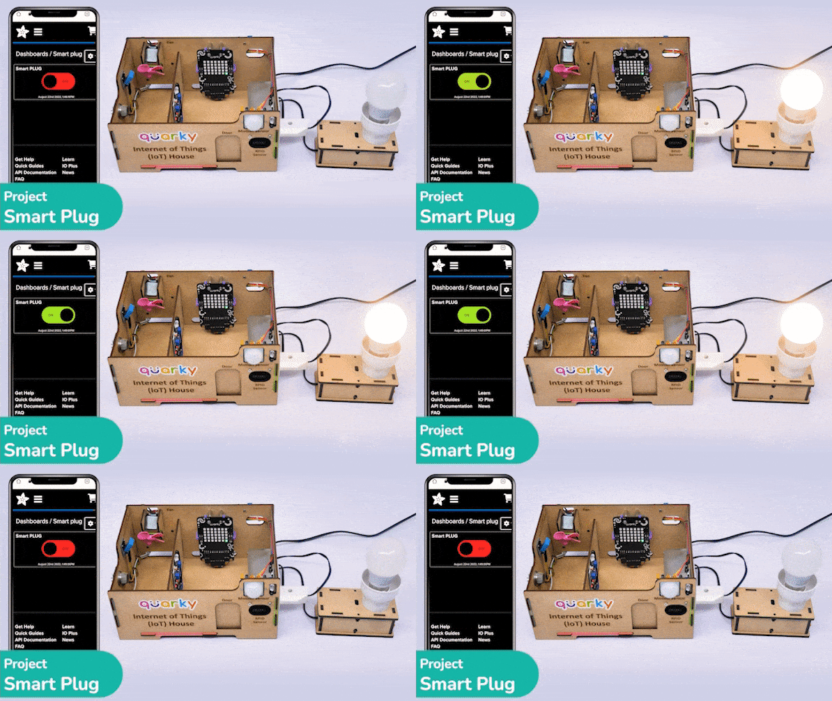
Creating a Switch on Adafruit IO

We will be using Adafruit IO for creating a switch on the cloud. Follow the instructions:

  1. Create a new Feed named Light.
  2. Create a new Dashboard named Light Control.
  3. Edit the Dashboard and add a Toggle Block.
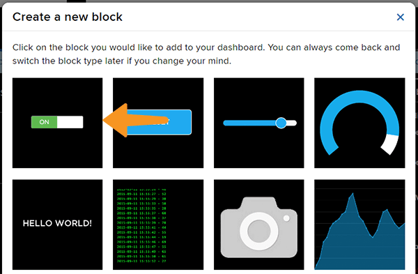
  4. Connect the Light feed to the block and click on Next Step.
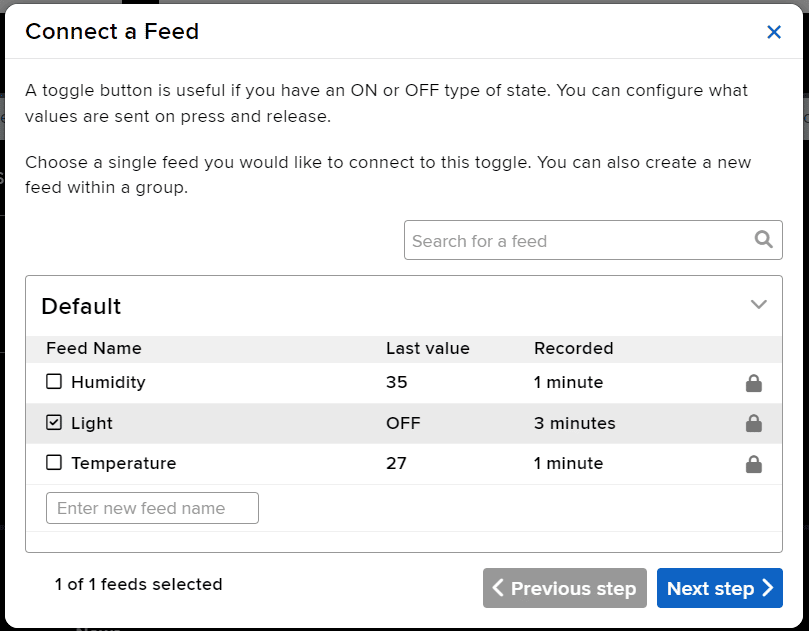
  5. Edit the Block Setting and click on Create Block.
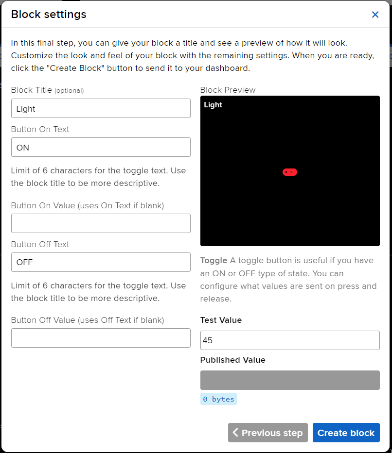
  6. Block is added. You can try to toggle the switch.
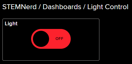
  7. Go to the Light feed. You will observe the value of the feed changing as we click on the switch on the Dashboard.

Adafruit IO Key

You can find the information about your account once you log in from here:
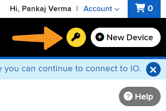
Note: Make sure you are login on Adafruit IO: https://io.adafruit.com/

Circuit For the Lamp

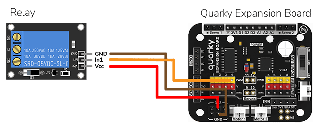
The bulb is connected to the smart plug which is controlled with a relay.

Note:  A relay is an electromechanical switch that is used to turn on or turn off a circuit by using a small amount of power to operate an electromagnet to open or close a switch.

If the relay is ON, the smart switch gets ON, turning on the light. The relay has the following connections:

  1. GND Pin connected to GND of the Quarky Expansion Board.
  2. VCC Pin connected to VCC of the Quarky Expansion Board.
  3. Signal Pin connected to Servo 4 of the Quarky Expansion Board.

Python Code for Stage Mode

This Python code connects to Adafruit IO using the given credentials and checks if the light is ON or OFF. If the light is ON, then the code sets the relay to 0 (ON) and sets the LED to white with a brightness of 100. If the light is OFF, then the code sets the relay to 1 (OFF) and sets the LED to black with a brightness of 100. The code runs in an infinite loop to continuously check the status of the light.

#This code is used to control the light in an IOT house. 
#The code connects to Adafruit IO using the given credentials and checks if the light is "ON" or "OFF". 
#If the light is "ON" then the code sets the relay to 0 (ON) and sets the LED to white with a brightness of 100. 
#If the light is "OFF" then the code sets the relay to 1 (OFF) and sets the LED to black with a brightness of 100. 

quarky = Quarky() #Creating an object for the Quarky class

adaio = AdaIO() #Creating an object for the AdaIO class
house = IoTHouse() #Creating an object for the IoTHouse class

adaio.connecttoadafruitio("STEMNerd", "aio_UZBB56f7VTIDWyIyHX1BCEO1kWEd") # Connecting to Adafruit IO using the given credentials 

while True: # Loop that runs forever
  if (adaio.getdata("Light") == "ON"): #Checking if the light is "ON"
    house.setrelay(0, "pwm4") # Setting the relay to 0
    quarky.setled(1, 1, [255, 255, 255], 100) #Setting the LED to white with a brightness of 100

  if (adaio.getdata("Light") == "OFF"): #Checking if the light is "OFF"
    house.setrelay(1, "pwm4") # Setting the relay to 1
    quarky.setled(1, 1, [0, 0, 0], 100) #Setting the LED to black with a brightness of 100


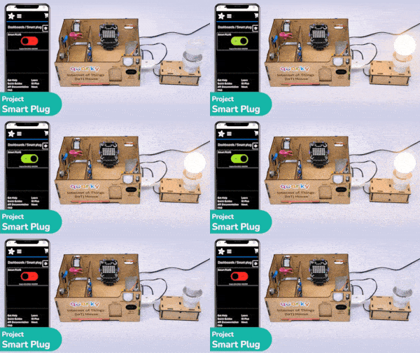
Output

IoT-Enabled Smart Plug Upload Mode

You can also make the IoT Enabled Smart Plug work independently of PictoBlox using the Upload Mode. For that switch to upload mode and replace the when green flag clicked block with when Quarky starts up the block.

This code connects to a wifi network and an Adafruit IO account, creates an object for the IoTHouse class, and then sets a relay and LED based on the data from the Adafruit IO account. The loop runs forever and will always check if the wifi is connected and if the light isON orOFF“. If the wifi is not connected, it will set the LED to red.

from quarky import *

# Connect to a wifi network
import iot
import iothouse
wifi = iot.wifi()
wifi.connecttowifi("IoT", "12345678")

# Connect to an adafruit IO account
adaio = iot.AdaIO()
adaio.connecttoadafruitio("STEMNerd", "aio_UZBB56f7VTIDWyIyHX1BCEO1kWEd")

#Creating an object for the IoTHouse class
house = iothouse.iothouse()

while True:  # Loop that runs forever
  # Check if the wifi is connected
  if wifi.iswificonnected():
    if (adaio.getdata("Light") == "ON"):  #Checking if the light is "ON"
      house.setrelay(0, "pwm4")  # Setting the relay to 0
      quarky.setled(1, 1, [255, 255, 255], 100)  #Setting the LED to white with a brightness of 100

    if (adaio.getdata("Light") == "OFF"):  #Checking if the light is "OFF"
      house.setrelay(1, "pwm4")  # Setting the relay to 1
      quarky.setled(1, 1, [0, 0, 0], 100)  #Setting the LED to black with a brightness of 100

  else:
    # Set LED 1 to red
    quarky.setled(1, 1, [255, 0, 0], 100)


Read More
Learn how to create an IoT House Monitoring System that sends humidity, temperature, plant soil moisture, gas, and light sensor data to the cloud on Adafruit IO servers in PictoBlox Python Environment. Get step-by-step instructions on creating a dashboard with sensors and more.

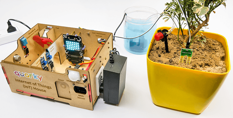
This example shows how to create an IoT House Monitoring system that sends humidity, temperature, plant soil moisture, gas, and light sensor data to the cloud on Adafruit IO servers in PictoBloc Python Environment.

Adafruit IO Key

You can find the information about your account once you log in from here:
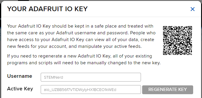
 

Adafruit IO Key

You can find the information about your account once you log in from here:

Note: Make sure you are login on Adafruit IO: https://io.adafruit.com/

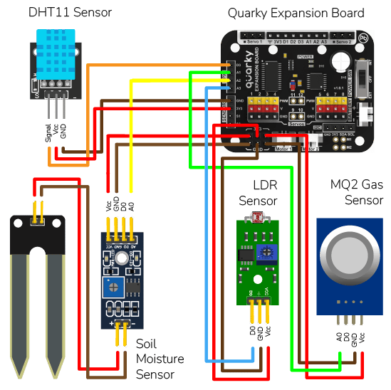
Sensor Connection to Quarky

We are using 4 sensors in this project:

  1. DHT sensors have 3 pins: GND, VCC, and Signal. You have to connect the following 3 pins to the Quarky Expansion Board:
    1. GND to Ground Pin of Quarky Expansion Board
    2. VCC to 3.3V or VCC Pin of Quarky Expansion Board
    3. Signal to the D3 (Digital Pin) of the Quarky Expansion Board
  2. LDR sensors have 4 pins: GND, VCC, DO, and AO. You have to connect the following 3 pins to the Quarky Expansion Board:
    1. GND to Ground Pin of Quarky Expansion Board
    2. VCC to 3.3V or VCC Pin of Quarky Expansion Board
    3. AO to the A3 (Analog Pin) of the Quarky Expansion Board
  3. The gas sensor has the following connections:
    1. GND Pin connected to GND of the Quarky Expansion Board.
    2. VCC Pin connected to VCC of the Quarky Expansion Board.
    3. AO (Signal Pin) connected to Analog Pin A1 of the Quarky Expansion Board
  4. Moisture Sensor: The moisture sensor provides real-time moisture reading from the soil. The moisture sensor connections are as follows:
    1. GND Pin connected to GND of the Quarky Expansion Board.
    2. VCC Pin connected to VCC of the Quarky Expansion Board.
    3. AO (Signal Pin) connected to Analog Pin A2 of the Quarky Expansion Board

Python Code

# The following code connects to a device, reads sensor values and sends them to a data storage.
# First, the necessary packages are imported.
import time
import math

# Then, three objects are created: one for the IoT house with the sensors and one for the AdaIO and one for Quarky.
house = IoTHouse()
adaio = AdaIO()
quarky = Quarky()

# Variables used by the code are created and initialized.
RS_of_Air = 0
R0 = 0
b = 1.413
m = -0.473

# User Defined Functions

# This function calibrates the gas sensor.
def Get_RO_Calibrated():
  Sensor_Value = 0.1
  # This loop reads the sensor value 20 times.
  for i in range(0, 20):
    Sensor_Value += house.gassensorvalue("A1")
  # This line calculates the average of the 20 readings.
  Sensor_Value = (Sensor_Value / 20)
  
  # This line calculates the RS_of_Air variable.
  RS_of_Air = ((4095 - Sensor_Value) / Sensor_Value)
  
  # This line calculates the R0 variable.
  R0 = (RS_of_Air / 9.8)
  time.sleep(1)


# This function reads the gas sensor.
def Get_Gas_Sensor_Reading():
  # This line reads the sensor value.
  Sensor_Value = house.gassensorvalue("A1")
  # This line checks if the sensor value is 0.
  if (Sensor_Value == 0):
    # This line returns 0 if the sensor value is 0.
    return 0
  else:
    # This line calculates the RS_of_Air variable.
    RS_of_Air = ((4095 - Sensor_Value) / Sensor_Value)
    # This line calculates the RS_RO_Ratio variable.
    RS_RO_Ratio = (RS_of_Air / R0)
    # This line calculates the PPM_in_Log variable.
    PPM_in_Log = (((math.log(RS_RO_Ratio)) - b) / m)
    # This line calculates the PPM variable.
    PPM = (pow(10, PPM_in_Log))
    # This line returns the PPM value.
    return PPM

# This line calls the Get_RO_Calibrated() function.
Get_RO_Calibrated()

# This line connects the program to the AdaIO data storage.
adaio.connecttoadafruitio("STEMNerd", "aio_UZBB56f7VTIDWyIyHX1BCEO1kWEd")

# This line sets the pin to read the moisture sensor.
house.setmoisturepin("A3")

# This loop reads the sensors, prints their values and sends them to the data storage.
while True:
  # This line reads the temperature from the DHT sensor on pin D3 and sends it to the data storage.
  Temperature = house.dhtmeasure(1, "D3")
  adaio.createdata("Temperature", Temperature)
  time.sleep(4)
  
  # This line reads the humidity from the DHT sensor on pin D3 and sends it to the data storage.
  Humidity = house.dhtmeasure(2, "D3")
  adaio.createdata("Humidity", Humidity)
  time.sleep(4)
  
  # This line reads the light from the light sensor on pin A2 and sends it to the data storage.
  Light = house.ldrvalue("A2")
  adaio.createdata("Light", Light)
  time.sleep(4)
  
  # This line reads the moisture from the moisture sensor and sends it to the data storage.
  Moisture = house.readmoisture()
  adaio.createdata("Moisture", Moisture)
  time.sleep(4)
  
  # This line calls the Get_Gas_Sensor_Reading() function to read the gas sensor and sends the value to the data storage.
  PPM = Get_Gas_Sensor_Reading()
  adaio.createdata("Gas Sensor", PPM)
  time.sleep(4)

Creating Dashboard

Follow the steps:

  1. Go to the dashboard and click on New Dashboard.
  2. Add the Dashboard Name and Description and click on Create.
  3. Open the New Dashboard. Click on the Setting icon in the top right corner and then click on Create New Block.
  4. From the options, click on the line chart.
  5. Select the Temperature Feed and click on Next Step.
  6. Add the Block Title and the Y-Axis Minimum – Maximum value. Click on Create Block.
  7. You will find the block added on the dashboard.
  8. Add other blocks for the Humidity, Light, Gas, and Moisture as well.
  9. Click on the Setting button and Edit Layout to align all the buttons.
Read More
All articles loaded
No more articles to load