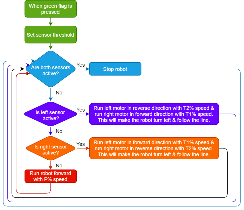
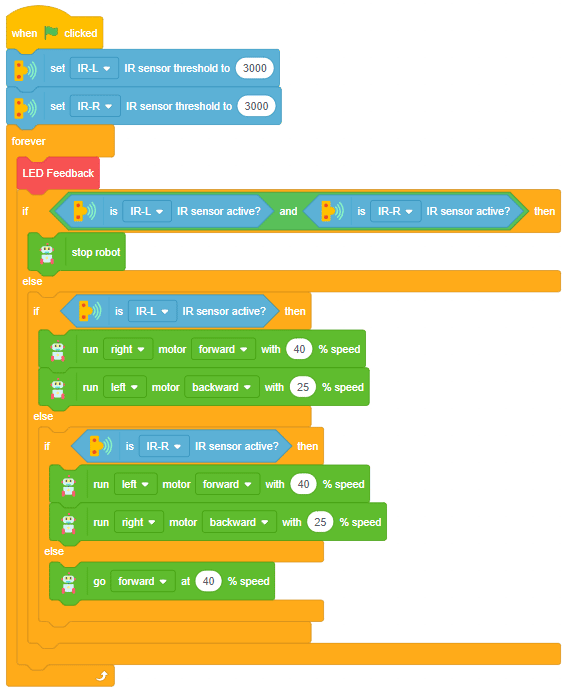
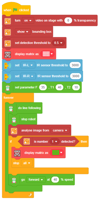
Alert: You need to calibrate the IR sensor to get the best line detection by the robot. Also, you need to calibrate the speeds to make the robot follow the line correctly.
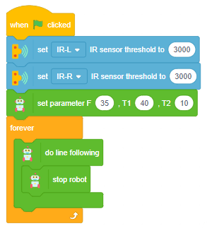
Alert: You need to calibrate the IR sensor to get the best line detection by the robot. Also, you need to calibrate the speeds to make the F, T1 and T2 speeds for the robot to follow the line correctly.
Alert: You need to calibrate the IR sensor to get the best line detection by the robot. Also, you need to calibrate the speeds to make the robot follow the line correctly.
Learn how to control the Mecanum using PictoBlox with keyboard inputs. Make the Mecanum move forward, backward, turn left, and turn right along with unique lateral motions!
In this activity, we will make the computer program that controls the Mecanum Robot. It’s like a remote-control car. You can press different keys on the keyboard to make the Mecanum move forward, backward, left and right.
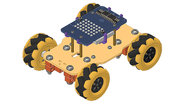
The Quarky Mecanum Wheel Robot is a type of robot that uses a special type of wheel to move. The wheel is made of four rollers mounted at 45-degree angles to the wheel‘s hub. Each roller has its own motor and can spin in either direction. This allows the wheel to move in any direction, making it an ideal choice for navigating around obstacles and tight spaces. The mecanum wheel robot can also turn on the spot, allowing it to make sharp turns without having to reverse direction.
Coding Steps
Follow the steps:
Open a new project in PictoBlox.
Connect Quarky to PictoBlox.
Click on the Add Extension button and add the Quarky Mecanum extension.
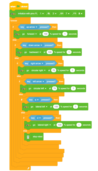
Now we will first initialize the Mecanum robots and the servos before starting the main code.
The main code will consist nested if-else conditions that will check specific conditions on which key is pressed, and will react accordingly. We will use the arrow keys for basic movements (Forward, Backward, Left Right) and the keys “a” for lateral left movement and “d” for lateral right movement.
Learn how to build a high-performance, wireless control system for your robot for Grade 5 using Quarky and PictoBlox’s Dabble extension. In this project, students will learn how to interface a digital gamepad to command the robot’s movement in all directions.
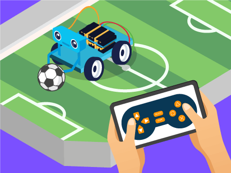
Have you ever wanted to build your own remote-controlled robot — just like the autonomous robots used in warehouses, disaster zones, and space exploration? In this exciting STEM and robotics project, we will program the Quarky robot to be fully controlled by a gamepad controller using PictoBlox’s Block Coding mode. No complex wiring, no advanced programming experience needed — just drag, drop, and drive!
Using the Quarky Expansion Board and PictoBlox’s Dabble extension, we will write a block-coded script that makes Quarky move forward, backward, left, and right; control individual motors; and stop safely — all from the buttons on a gamepad. This is your first step into the world of AI-powered robotics and human-machine interaction!
Prerequisites
Step 1
Quarky robot
Quarky Expansion Board
Dabble app in your mobile
A stable Bluetooth or USB connection between PictoBlox and Quarky
Laptop
Step 2:
Click the Add Extension button (the purple icon at the bottom left of the screen). Search for Dabble and Quarky expansion board and add it to your project.
This project only runs in Upload mode only; make sure you are in Upload mode.
Step 3
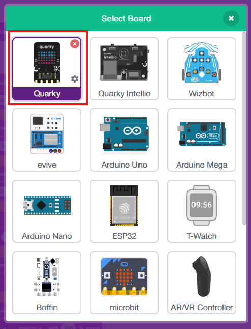
Click on the Board tab on the top navigation bar and select Quarky.
Now, click on connect and choose Bluetooth.
Your Quarky has a unique code mentioned on it. Select your Quarky from the list and click on Connect.
Quarky plays a confirmation sound on connecting.
Voila! Your Quarky is now connected to PictoBlox!
Remove the Tobi sprite.
How It Works
The script runs inside a forever loop that continuously checks which gamepad button is currently being pressed. Based on the button detected, a specific movement command is sent to the Quarky robot. This is called real-time polling — a technique used in robotics, game development, and AI systems to read and react to input states every few milliseconds.
Block-by-Block Guide
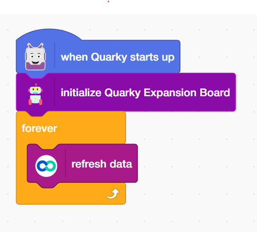
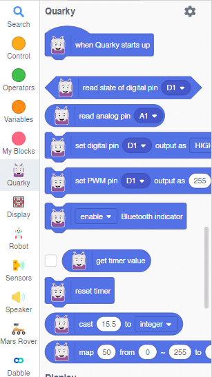
Initialization (When Quarky Starts Up)
Add the ‘When Quarky starts up’ block from the Quarky palette. The script begins with the ‘When Quarky starts up’ block from the Quarky palette trigger block. This is the entry point of the entire programme. Everything that follows runs automatically when Quarky is switched on and the script is started in PictoBlox.
Add the ‘Initialise Quarky Expansion Board’ block, which sets up communication between PictoBlox and the physical Quarky Expansion Board, enabling motor control, sensor reading, and gamepad input.
Add the ‘Forever’block from the Control Palette. It wraps the entire control logic in an infinite loop so that Quarky continuously checks for gamepad inputs and reacts without any delay or gap.
Add the ‘Refresh Data’ block from the Dabble extension. Updates all sensor and controller data at the start of each loop cycle, ensuring Quarky is always responding to the most current gamepad state.
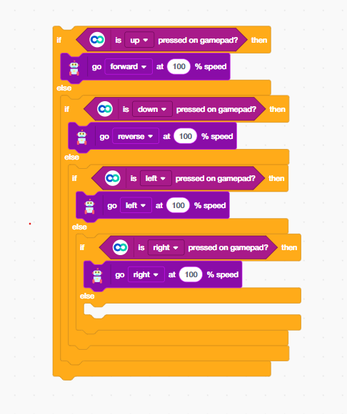
Move Forward (Up Button)
The first conditional checks whether the Up button on the gamepad is pressed. If true, Quarky moves forward at full speed.
Add an ‘if-else’ block from the control palette.
Add the ‘is up pressed on gamepad?’ block from the Dabble extension inside the If block.
Add the ‘go forward at 100% speed’ block from the Quarky Expansion Board Extension, drives both of Quarky’s motors in the forward direction at maximum power. You can reduce the percentage for slower, more precise movement.
Move Backward (Down Button)
The second conditional checks whether the down button on the gamepad is pressed. If true, Quarky moves Backward at full speed.
Add an ‘if-else’ block from the control palette inside the previous if-else block.
Add the ‘is up pressed on gamepad?’ block from the Dabble extension inside the If block. Change the dropdown to down.
When the backward button is pressed, Quarky reverses direction and moves backward. Add ‘go reverse at 100% speed’ block, reverses both motors simultaneously, moving Quarky away from an obstacle or back to a starting position.
Turn Left (Left Button)
The third conditional checks whether the left button on the gamepad is pressed. If true, Quarky moves left at full speed.
Add an ‘if-else’ block from the control palette inside the previous if-else block.
Add the ‘is left pressed on gamepad?’ block from the Dabble extension inside the If block. Change the dropdown to Left.
When the Down button is pressed, Quarky reverses direction and moves backward. Add the ’go left at 100% speed’ block, commands Quarky to execute a left turn. In differential drive robots like Quarky, turning is achieved by running one motor faster or in reverse relative to the other.
Turn Right (Right Button)
The forth conditional checks whether the right button on the gamepad is pressed. If true, Quarky moves left at full speed.
Add an ‘if-else’ block from the control palette inside the previous if-else block.
Add the ‘is right pressed on gamepad?’ block from the Dabble extension inside the If block. Change the dropdown to Left.
When the Down button is pressed, Quarky reverses direction and moves backward. Add the ’go right at 100% speed’ block, executes a right turn. Combined with the left turn command, this gives Quarky full rotational control — essential for navigating tight spaces and corridors.
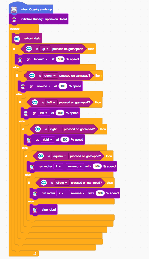
Control Motor 1 Backward (Square Button)
The next conditional checks whether the square button on the gamepad is pressed. If true, the Square button provides individual motor control — a more advanced movement option that allows fine-tuned directional adjustments beyond standard forward/backward/turn commands.
Add an ‘if-else’ block from the control palette inside the previous if-else block.
Add the ‘is up pressed on gamepad?’ block from the Dabble extension inside the If block. Change the dropdown to Square.
Add the ’run motor 1 backward with 100% speed’ block; it directly controls Motor 1 on the Quarky Expansion Board independently. Individual motor control is used in advanced robotics for tank-style turning, articulated arm movement, and multi-axis control systems.
Control Motor 2 Backward (Circle Button)
Similarly, the Circle button controls Motor 2 independently, enabling asymmetric movement for complex tasks.
Add an ‘if-else’ block from the control palette inside the previous if-else block.
Add the ‘is up pressed on gamepad?’ block from the Dabble extension inside the If block. Change the dropdown to Circle.
Add the ’run motor 2 backward with 100% speed, controls the second motor independently. Running Motor 1 and Motor 2 at different speeds or in different directions is the key technique behind differential drive steering, the same method used in NASA Mars rovers and autonomous delivery robots.
Stop the Robot (No Button Pressed)
Add ‘stop robot’ block, sends a stop signal to all motors, bringing Quarky to a complete halt. In AI-controlled robots, having a reliable stop condition prevents runaway behaviour and is a core requirement of safe autonomous systems design.
Connect your Quarky with Dabble
Connect your Quarky to Dabble → Open Gamepad → Start controlling your Quarky Robo Soccer!
Output
Conclusion
Congratulations! You have successfully programmed the Quarky robot to respond to gamepad input using PictoBlox Block Coding. In this project, you:
Initialized Quarky and its Expansion Board for hardware communication
Built a real-time control loop using the Forever block
Mapped 6 gamepad buttons to 6 distinct robot movement commands
Implemented individual motor control for advanced directional movement
Added a safe stop condition to ensure the robot halts when no input is detected
These skills — real-time input polling, conditional logic, motor control, and fail-safe design — are the exact same building blocks used by robotics engineers and AI developers around the world. You are not just playing with a robot; you are learning the language of machines!
In this activity, we will control the Mars Rover according to our needs using the Dabble application on our own Devices.
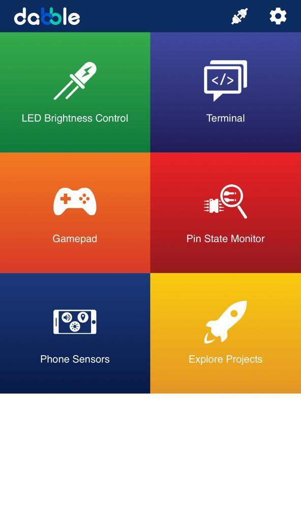
We will first understand how to operate Dabble and how to modify our code according to the requirements. The following image is the front page of the Dabble Application.
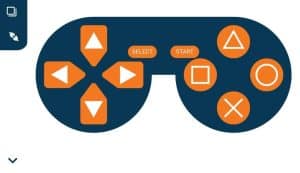
Select the Gamepad option from the Home Screen and we will then use the same gamepad to control our Mars Rover.
Code
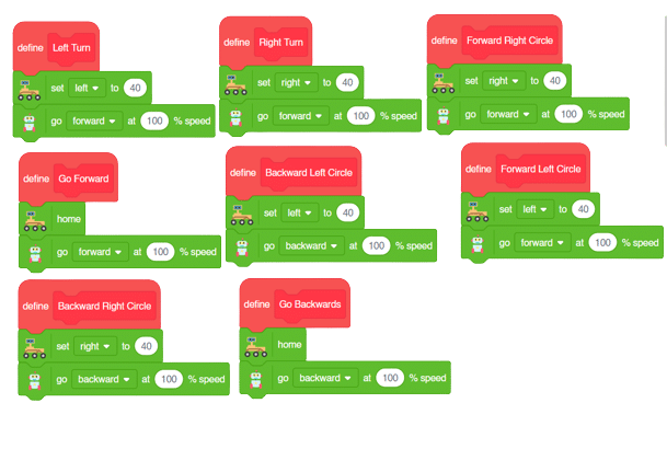
The following blocks represent the different functions that are created to control the Mars Rover for different types of motions. We will use the arrow buttons to control the basic movements.( Forward, Backward, Left, Right )
We will create our custom functions for specialized Circular motions of Mars Rover. We will use the Cross, Square, Circle, and Triangle buttons to control the Circular motions of Mars Rover.
Note: You will have to add the extensions of Mars Rover and also of Dabble to access the blocks.
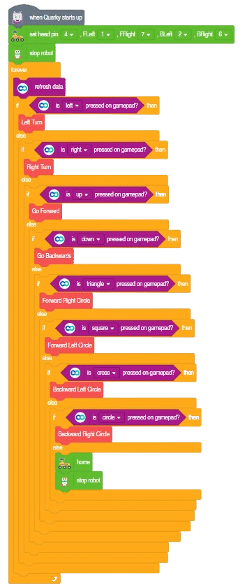
The main code will be quite simple consisting of nested if-else loops to determine the action when a specific button is pressed on the Dabble Application.
You will have to connect the Quarky with the Dabble Application on your device. Make sure Bluetooth is enabled on the device before connecting. Connect the Rover to the Dabble application after uploading the code. You will be able to connect by clicking on the plug option in the Dabble Application as seen below. Select that plug option and you will find your Quarky device. Connect by clicking on the respective Quarky.
Important Notes
The code will only run by uploading the code by connecting the rover with the help of a C-Type Cable to the Laptop.
You will be able to upload the Python Code by selecting the Upload option beside the Stage option.
There may be a case where you will have to upload the firmware first and then upload the code to the Rover. You will be able to upload the firmware in Quarky with the help of the following steps:
Select the Quarky Palette from the Block Section.
Select the Settings button on top of the palette.
In the settings dialog box, scroll down, and select the Upload Firmware option. This will help you to reset the Quarky if any previous code was uploaded or not.
After the Firmware is uploaded, click on the “Upload Code” option to upload the code.
You will have to add the block “When Quarky Starts Up” rather than the conventional “When Green Flag is Clicked” for the code to run.
Explore the surroundings with our obstacle avoidance Mars Rover that uses an ultrasonic sensor to detect and avoid obstacles. Learn how the robot moves, detects obstacles, and navigates its way through them.
This project of obstacle avoidance is for a robot that will move around and look for obstacles. It uses an ultrasonic sensor to measure the distance. If the distance is less than 20 cm, it will stop and look in both directions to see if it can move forward. If it can, it will turn left or right. If not, it will make a U-turn.
Logic
This code is making a robot move around and explore its surroundings. It has an ultrasonic sensor that can measure the distance between objects.
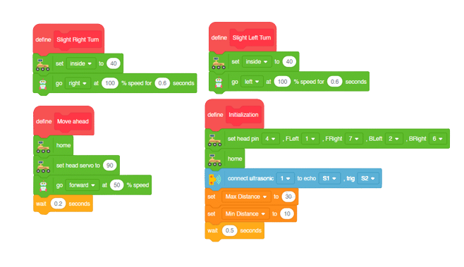
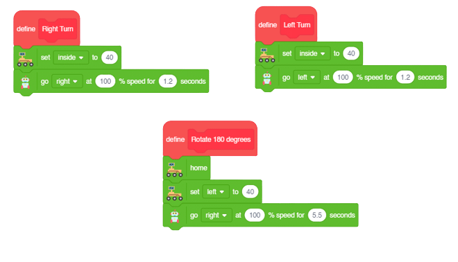
We will first initialize the servos of the Mars Rover with the block “Set head pins()”.
Then we will make all the servos rotate to 90 degrees if they are not initialized.
Thereafter we will initialize the ultrasonic sensors and define the minimum and maximum distance variables.
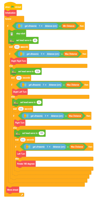
The main logic of the code is that it first checks whether the distance is less than the minimum distance. If it is, the head servo will move to 45 degrees and check again if the distance is greater than the maximum distance, hence moving in the right direction.
The robot with the help of the head servo, will check the distance for the conditions 90 degrees, 45 degrees, 135 degrees, 0 degrees and 180 degrees in the same order as stated.
Whenever the distance measured will be less than minimum distance the head servo will change the direction to the next set of degree to check distance.
In the last case scenario where all the angles contain obstacles as such, in that case the robot will change its direction to reverse by rotating to 180 degrees. By this way the robot will be able to navigate its own way through each and every obstacles.
Learn how to code logic for speech recognized control of Mars Rover with this example block code. You will be able to direct your own Mars Rover easily by just speaking commands.
Learn how to code logic for speech recognized control of Mars Rover with this example block code. You will be able to direct your own Mars Rover easily by just speaking commands.
Introduction
A speech recognized controlled Mars Rover robot is a robot that can recognize and interpret our speech, verbal commands, given by a human. The code uses the speech recognition model that will be able to record and analyze your speech given and react accordingly on the Mars Rover.
Speech recognition robots can be used in manufacturing and other industrial settings to control machinery, perform quality control checks, and monitor equipment.
They are also used to help patients with disabilities to communicate with their caregivers, or to provide medication reminders and other health-related information.
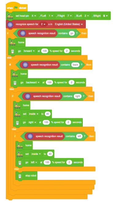
Main Code:
Logic
Firstly, the code initializes the Mars Rover pins and starts recording the microphone of the device to store the audio command of the user.
The code then checks conditions whether the command included the word “Go” or not. You can use customized commands and test for different conditions on your own.
If the first condition stands false, the code again checks for different keywords that are included in the command.
When any condition stands true, the robot will align itself accordingly and move in that direction of the respective command.
Learn how to create custom sounds to control Mars Rover with the Audio Classifier of the Machine Learning Environment in PictoBlox. Start building your Sound Based Controlled Mars Rover now!
In this activity, we will use the Machine Learning Environment of the Pictoblox Software. We will use the Audio Classifier of the Machine Learning Environment and create our custom sounds to control the Mars Rover.
Audio Classifier Workflow
Follow the steps below to create your own Audio Classifier Model:
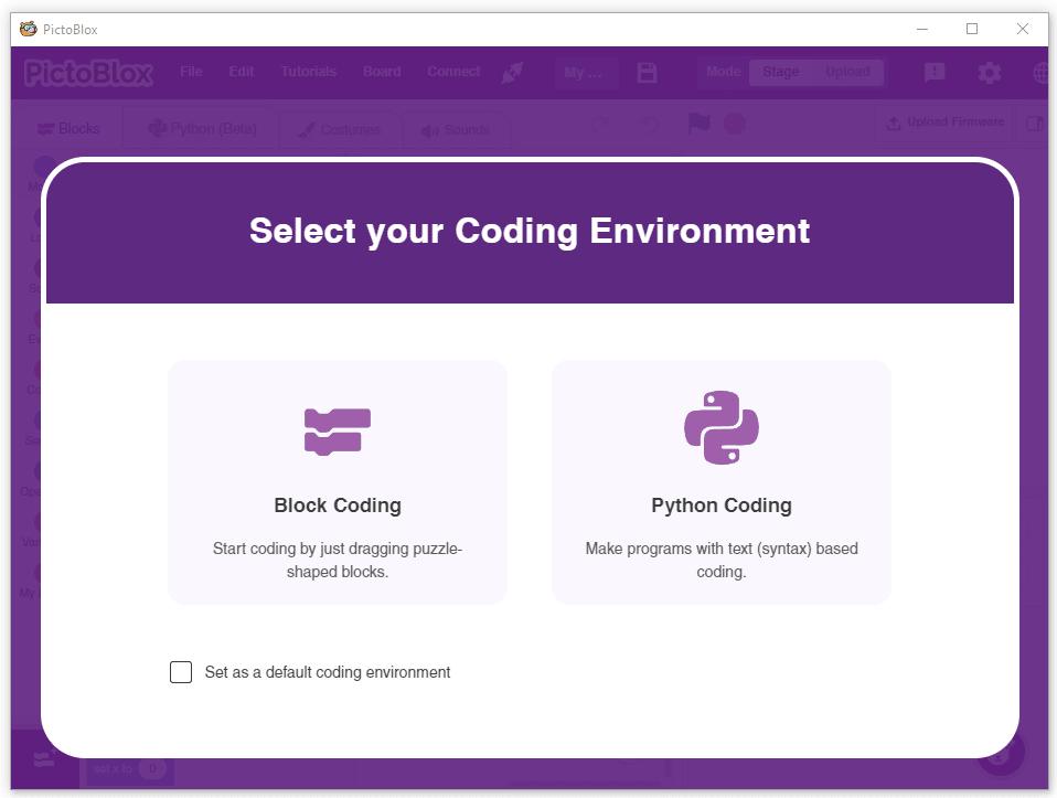
Open PictoBlox and create a new file.
Select the Block coding environment as appropriate Coding Environment.
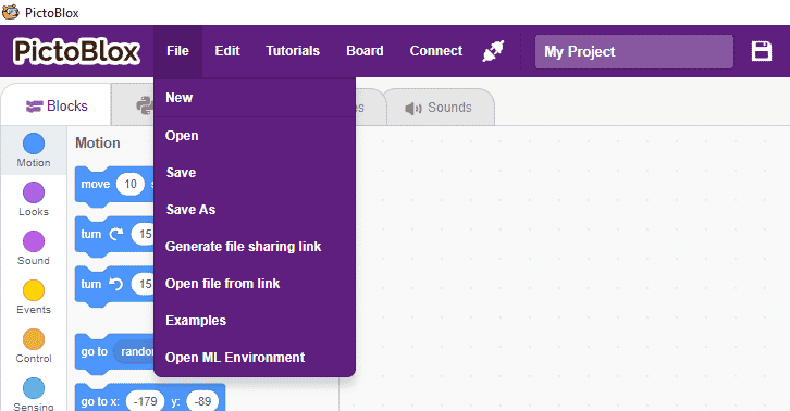
Select the “Open ML Environment” option under the “Files” tab to access the ML Environment.
Click on “Create New Project“.
A new window will open. Type in an appropriate project name of your choice and select the “Audio Classifier” extension. Click the “Create Project” button to open the Audio Classifier Window.
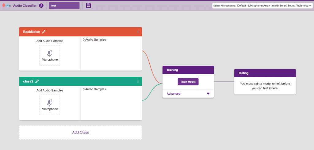
You shall see the Classifier workflow with two classes already made for you. Your environment is all set. Now it’s time to upload the data.
As you can observe in the above image, we will add two classes for audio. We will be able to add audio samples with the help of the microphone. Rename the class1 as “Clap” and class2 as “Snap”.
Note: You can add more classes to the projects using the Add Class button.
Adding Data to Class
You can perform the following operations to manipulate the data into a class.
Naming the Class: You can rename the class by clicking on the edit button.
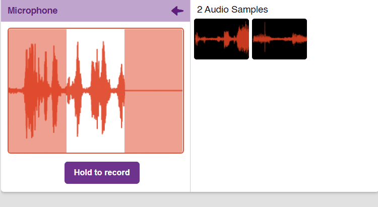
Adding Data to the Class: You can add the data using the Microphone.
You will be able to add the audio sample in each class and make sure you add atleast 20 samples for the model to run with good accuracy.
Add the first class as “clap” and record the audio for clap noises through the microphone.
Add the second class as “snap” and record the audio for snap noises through the microphone.
Note: You will only be able to change the class name in the starting before adding any audio samples. You will not be able to change the class name after adding the audio samples in the respective class.
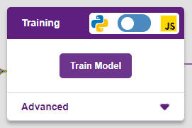
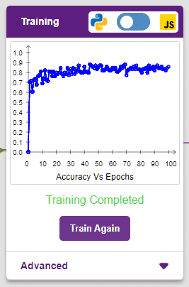
Training the Model
After data is added, it’s fit to be used in model training. In order to do this, we have to train the model. By training the model, we extract meaningful information from the hand pose, and that in turn updates the weights. Once these weights are saved, we can use our model to make predictions on data previously unseen.
The accuracy of the model should increase over time. The x-axis of the graph shows the epochs, and the y-axis represents the accuracy at the corresponding epoch. Remember, the higher the reading in the accuracy graph, the better the model. The range of the accuracy is 0 to 1.
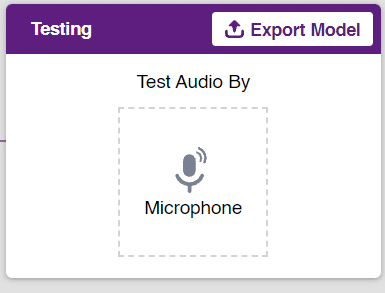
Testing the Model
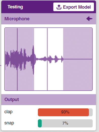
To test the model simply, use the microphone directly and check the classes as shown in the below image:
You will be able to test the difference in audio samples recorded from the microphone as shown below:
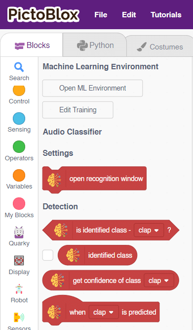
Export in Block Coding
Click on the “Export Model” button on the top right of the Testing box, and PictoBlox will load your model into the Block Coding Environment if you have opened the ML Environment in the Block Coding.
Logic
The Mars Rover will move according to the following logic:
When the audio is identified as “clap”- Mars Rover will move forward.
When the “snap” sound is detected –Mars Rover will move backward.
Note: You can add even more classes with different types of differentiating sounds to customize your control. This is just a small example from which you can build your own Sound Based Controlled Mars Rover in a very easy stepwise procedure.
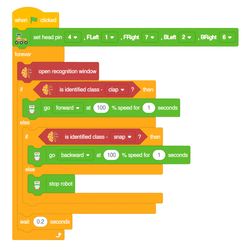
Code
Logic
First we will initialize different Audio classes.
Then, we will open the recognition window, which will identify different audio and turn on the microphone to identify and record the audio from the microphone.
If the identified class from the analyzed audio is “clap,” the Mars Rover will move forward at a specific speed.
If the identified class is “snap,” the Mars Rover will move backward.