Introduction
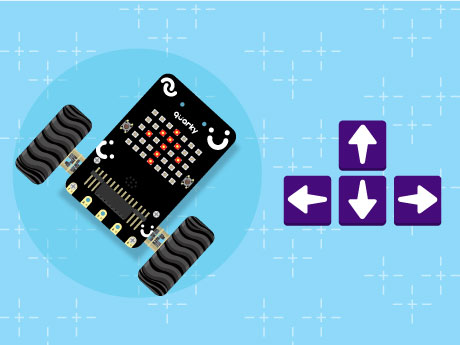
Have you ever wanted to control a robot using your computer keyboard — just like the robots used in automation labs, smart factories, and robotics competitions? In this fun and beginner-friendly robotics project, we will program the Quarky robot to move in different directions using the arrow keys in PictoBlox’s Block Coding mode. No complicated coding knowledge is required, just simple drag-and-drop blocks to bring your robot to life!
Using Quarky and PictoBlox, we will create a block-coded script that allows the robot to move forward, backward, left, and right while also displaying direction symbols on the RGB LED matrix Display for interactive visual feedback. The robot will even stop automatically when no key is pressed, making the control system smooth and user-friendly. This project is a great introduction to robotics control systems, human-machine interaction, and real-time input handling using block coding!
Prerequisites
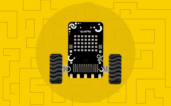
- Quarky
- Laptop
- PictoBlox installed on a Computer/Laptop
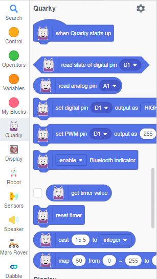
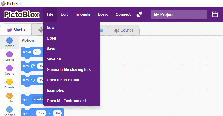
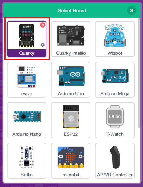
Connecting your Quarky to Pictoblox Blocks
- Click on the Board tab on the top navigation bar and select Quarky.
- Now, click on connect and choose Bluetooth
- Your Quarky has a unique code mentioned on it. Select your Quarky from the list and click on Connect.
4. Quarky plays a confirmation sound on connecting. Voila! Your Quarky is now connected to PictoBlox!
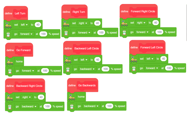
Block-by-Block Guide
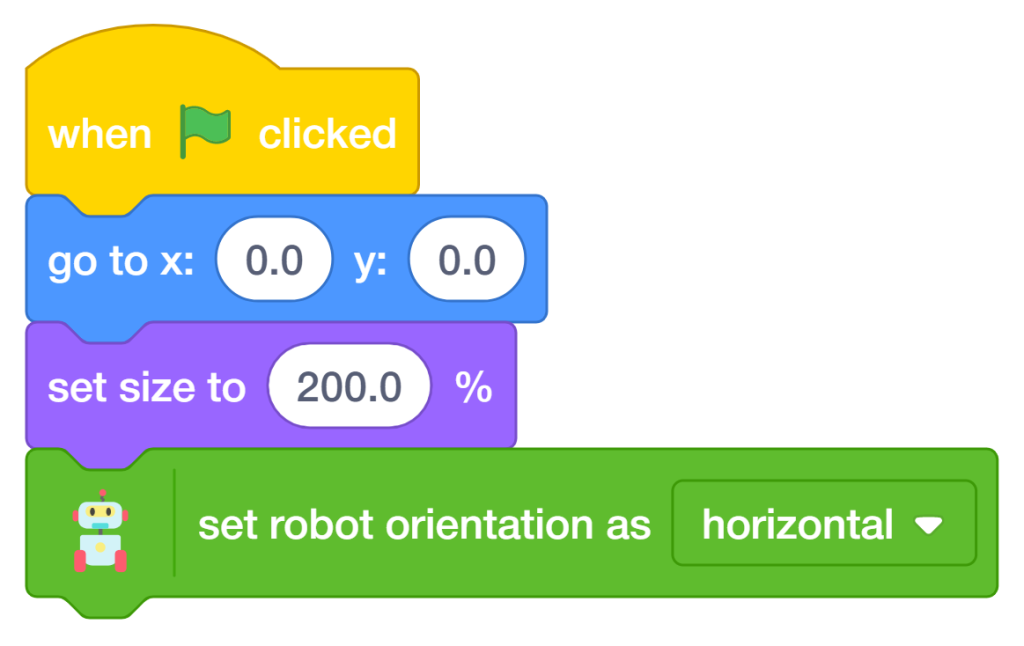
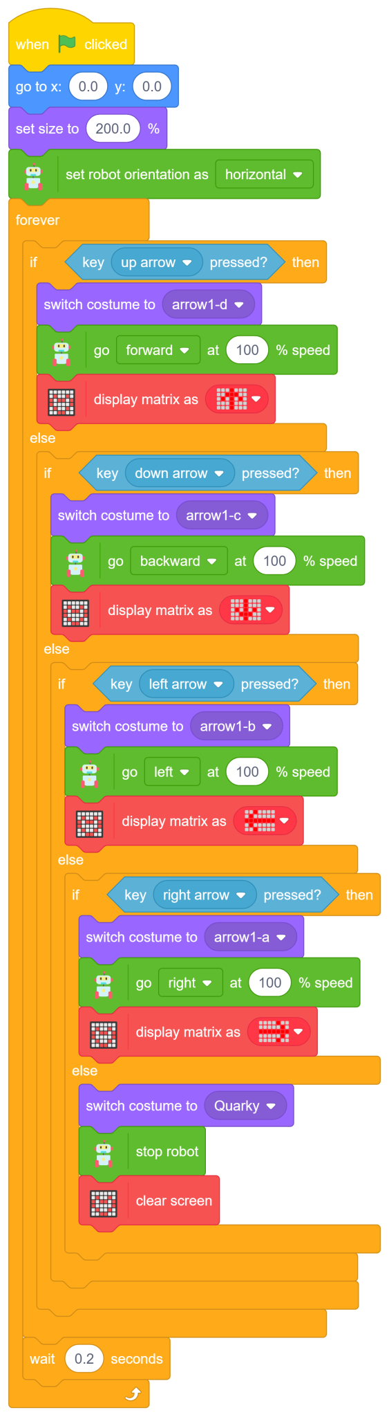
- When the green flag is clicked, the program starts running.
- The sprite first moves to the centre position (x:0, y:0), and its size is increased to 200% for better visibility on the stage.
Set Robot Orientation
- Use the ‘set robot orientation as horizontal to’ ensure correct robot movement direction.
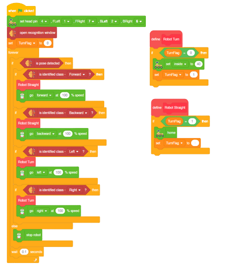
Move Forward (Up Arrow Key)
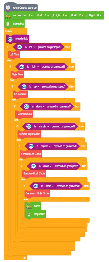
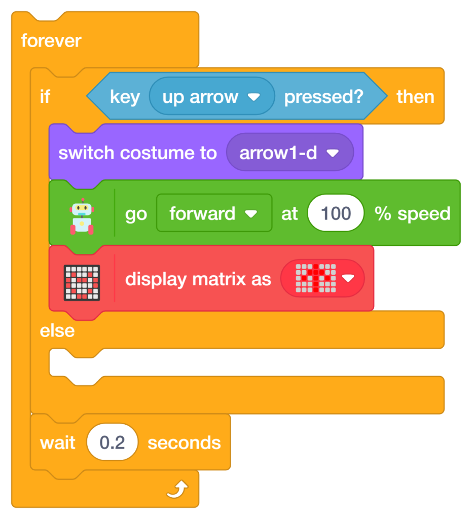
- Add a Forever Loop to continuously check keyboard inputs
The first conditional checks whether the up arrow key on the keyboard is pressed. If true, Quarky moves forward at full speed while displaying a forward direction symbol on the LED matrix.
- Add an ‘if-else’ block from the Control palette.
- Add the ‘key up arrow pressed’ block from the Sensing palette inside the If block.
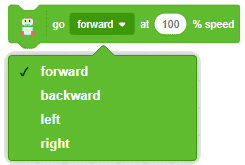
- Add the ‘go forward at 100% speed’ block from the Quarky Extension to move the robot forward.
- Add the ‘display matrix as’ the block to show a forward arrow symbol on the LED matrix.
- Add the ‘switch costume to (arrow1-d)’ block to visually indicate forward movement on the stage.
Move Backward (Down Arrow Key)
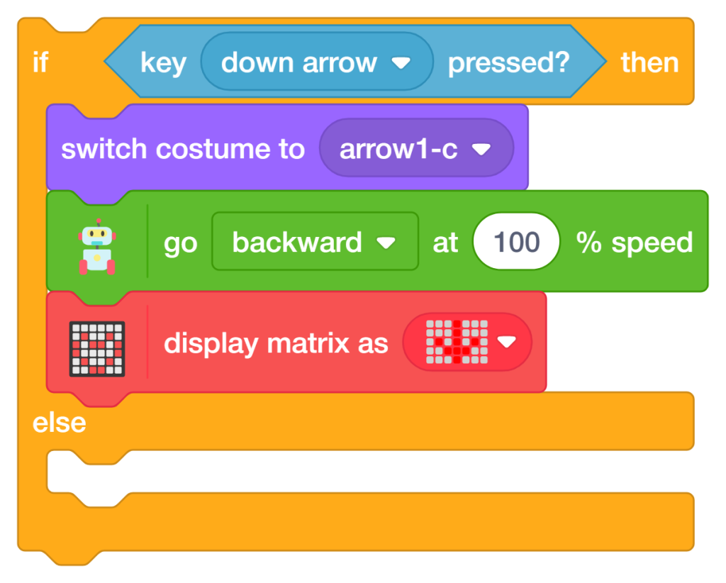
The second conditional checks whether the down arrow key is pressed. If true, Quarky moves backward at full speed and displays a backward direction symbol.
- Add another ‘if-else’ block inside the previous Else section.
- Add the ‘key down, arrow pressed?’ block and change the dropdown to a down arrow.
- Add the ‘go backward at 100% speed’ block to reverse the robot’s movement.
- Add the ‘display matrix as’ a block to show a backward arrow symbol on the LED matrix.
Add the ‘switch costume to (arrow1-c)’ block to indicate backward movement visually.
Turn Left (Left Arrow Key)
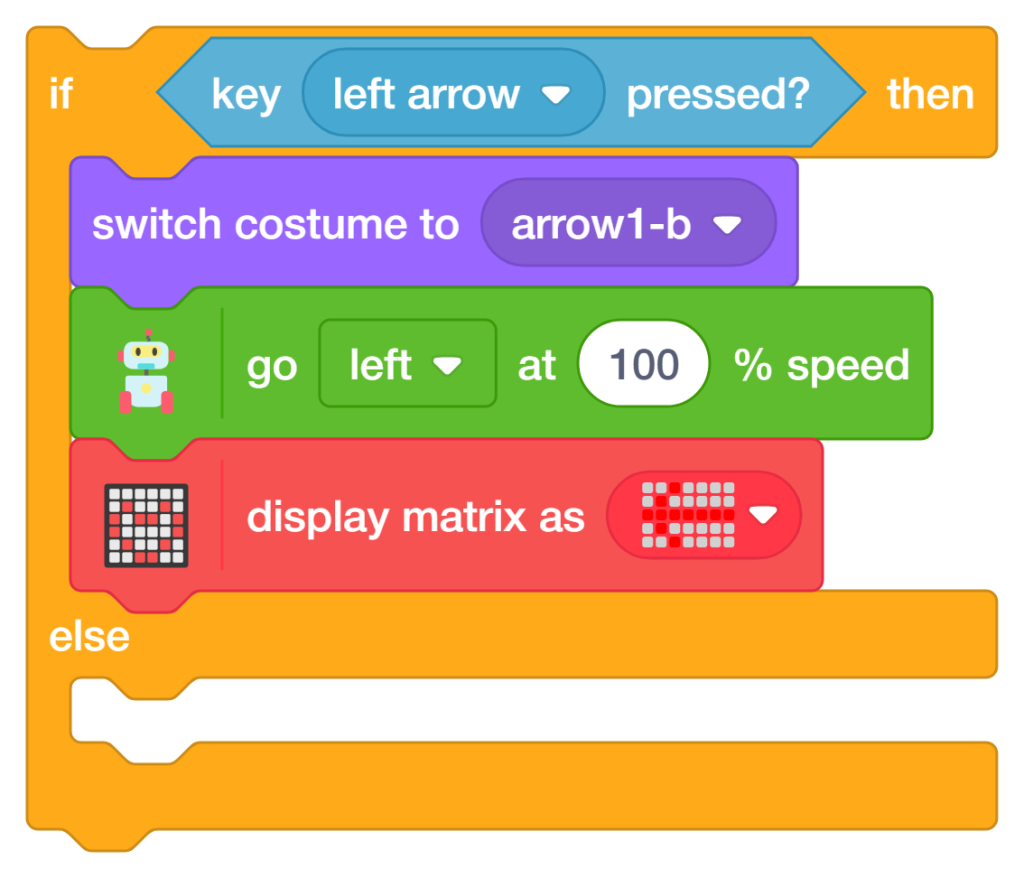
The third conditional checks whether the Left Arrow key is pressed. If true, Quarky moves left at full speed and displays a left direction symbol.
- Add another ‘if-else’ block inside the previous Else section.
- Add the ‘key left arrow pressed?’ block and change the dropdown to Left Arrow.
- Add the ‘go left at 100% speed’ block to make Quarky turn left.
- Add the ‘display matrix as’ block to show a left arrow symbol on the LED matrix.
- Add the ‘switch costume to (arrow1-b)’ block to visually indicate left movement.
Turn Right (Right Arrow Key)
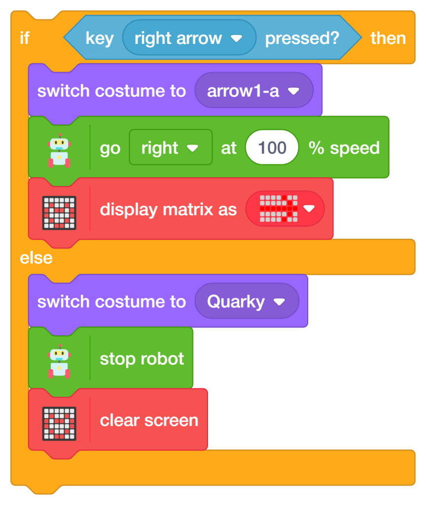
The fourth conditional checks whether the Right Arrow key is pressed. If true, Quarky moves right at full speed and displays a right direction symbol.
- Add another ‘if-else’ block inside the previous Else section.
- Add the ‘key right arrow pressed?’ block and change the dropdown to Right Arrow.
- Add the ‘go right at 100% speed’ block to make Quarky turn right.
- Add the ‘display matrix as’ block to show a right arrow symbol on the LED matrix.
- Add the ‘switch costume to (arrow1-a)’ block to visually indicate right movement.
Stop Robot (No Key Pressed)
The final Else condition checks whether none of the arrow keys are pressed. If true, Quarky stops moving, clears the LED matrix display, and switches back to its default costume. This prevents unnecessary movement and keeps the robot safe.
- Add the ‘stop robot’ block from the Quarky Extension inside the final Else section.
- Add the ‘clear LED matrix screen’ block to remove all direction symbols from the display.
- Add the ‘switch costume to Quarky’ block to restore the default robot appearance.
- This ensures the robot remains stationary when no keyboard input is detected.
Add a Small Delay
A small delay is added inside the ‘Forever loop’ to make the robot movement smoother and more stable.
- Add the ‘wait 0.2 seconds’ block from the Control palette at the end of the loop.
- This prevents the program from checking keyboard inputs too rapidly.
How to Run the Program
- Click the ‘Green Flag’ button in PictoBlox to start the program.
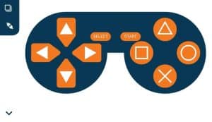
- Press the Arrow Keys on your keyboard to move Quarky in different directions.
- Observe the robot movement, costume changes, and LED matrix direction symbols in real time.
Output
Conclusion
Congratulations! You have successfully programmed the Remote Control Quarky robot to respond to arrow key inputs using PictoBlox Block Coding. In this project, you:
- Initialized Quarky and configured the robot orientation for accurate movement
- Built a real-time keyboard control system using the Forever loop
- Programmed Quarky to move forward, backward, left, and right using arrow keys
- Added visual feedback using different costumes and RGB LED matrix Display direction symbols
- Implemented an automatic stop condition when no key is pressed for safe navigation
These skills — keyboard input handling, conditional logic, robot navigation, RGB LED matrix display control, and real-time movement programming — are fundamental concepts used in robotics, automation systems, and AI-powered machines. You are not just controlling a robot; you are learning how intelligent machines interact with humans in real time!