


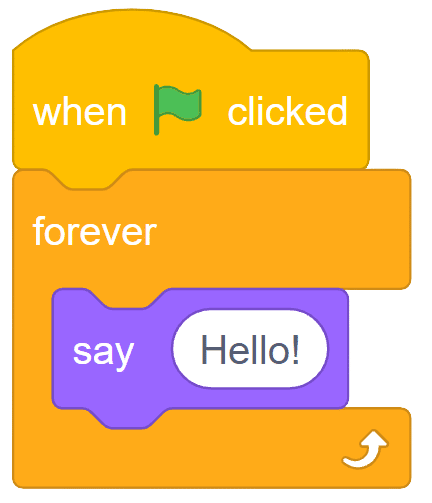
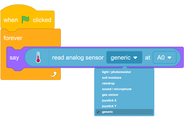
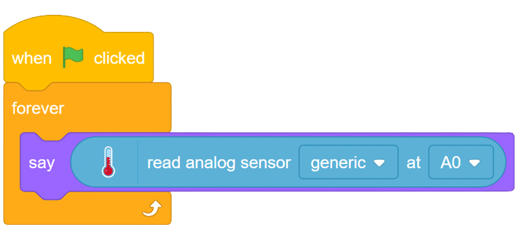
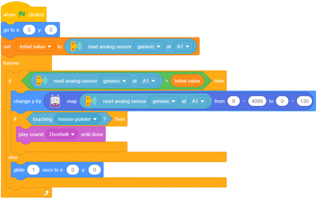
The block returns the analog reading of the sensor connected to the specified analog pin of the Quarky. The value varies between 0 to 4095.
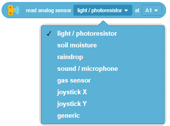
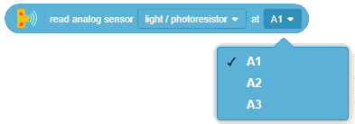
The block returns the analog reading of the sensor connected to the specified analog pin of the Quarky. The value varies between 0 to 4095.
LDR, also known as a Light Dependent Resistor, is an analog-type sensor renowned for its ability to modify its resistance based on the intensity of incident light. As the surrounding light changes, the resistance of the LDR fluctuates, making it an essential component in various light-sensing applications. While generally designed as a two-pin sensor, it is also available in a three-pin module, providing enhanced features and flexibility.

in this example, we will interface our sensor module with Arduino and we’ll be reading the change in it’s resistance upon the change of light.

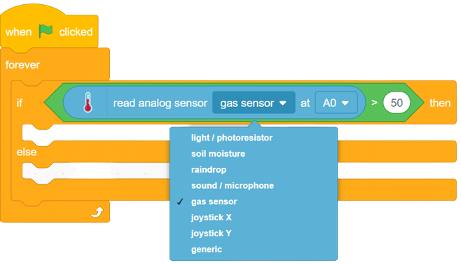
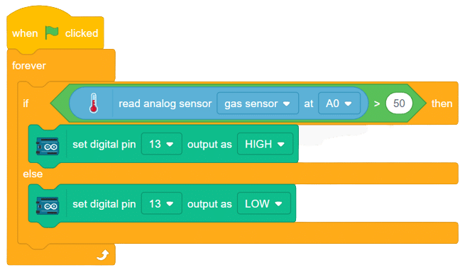
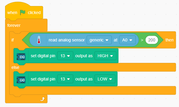
The MQ series of sensors offers a diverse range of gas detectors used for detecting multiple gases like CO2, LPG, and more. These sensors have numerous applications, from detecting smoke caused by fires in buildings to identifying gas leaks and natural gases in mining operations.
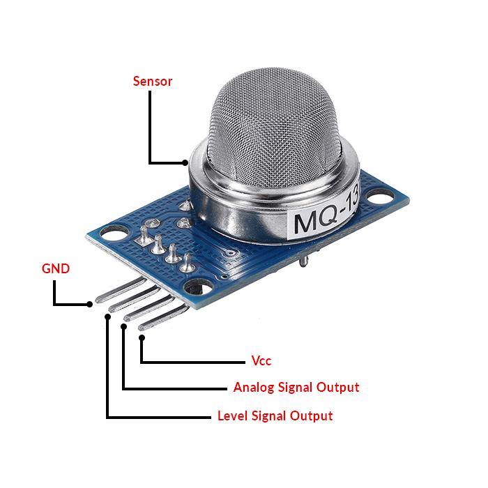
In this example, we will interface an MQ sensor with Arduino to detect gas levels above a certain threshold. When the gas levels surpass the set limit, Arduino will trigger a buzzer alarm. Let’s delve into the exciting world of gas detection using Arduino!
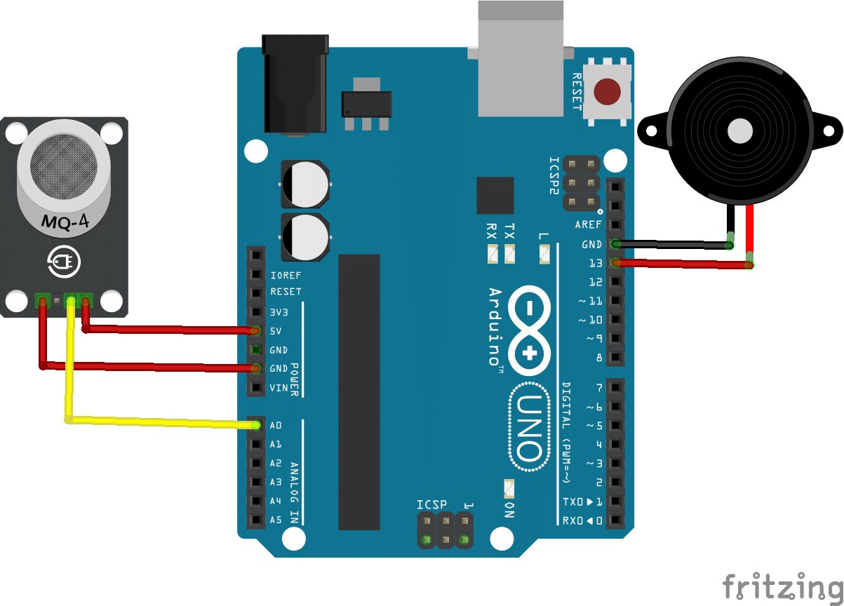
connection
Sensor Arduino
VCC 5V
GND GND
A0 A0
buzzer+ D13
Buzzer- GND

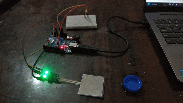
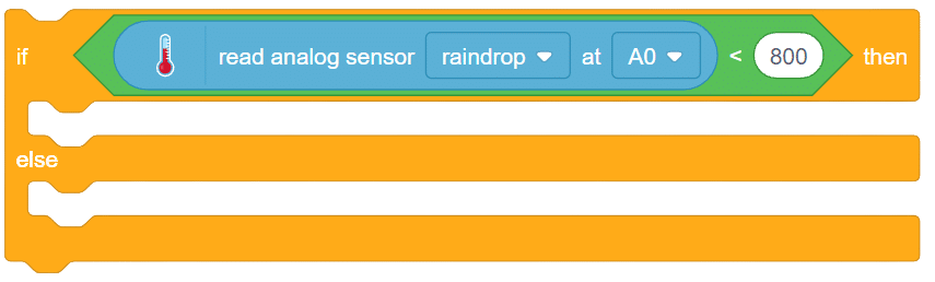
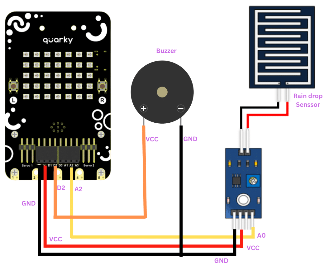
The raindrop sensor is an analog-type sensor that effectively measures changes in resistance when it encounters water. This property makes it an ideal choice for detecting rain and water presence in various applications. While typically designed with two pins, there are also versions available with a controller module, effectively converting it into a three-pin sensor for enhanced functionality.
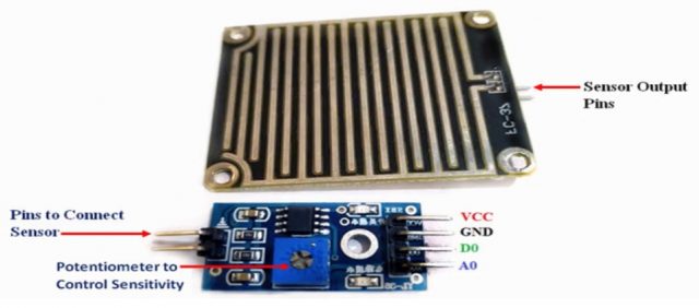
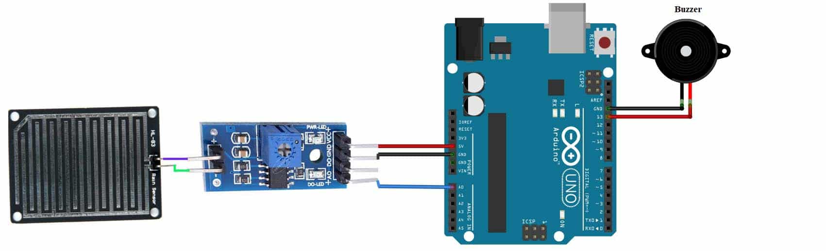
To set up the raindrop sensor circuit, make the following connections:
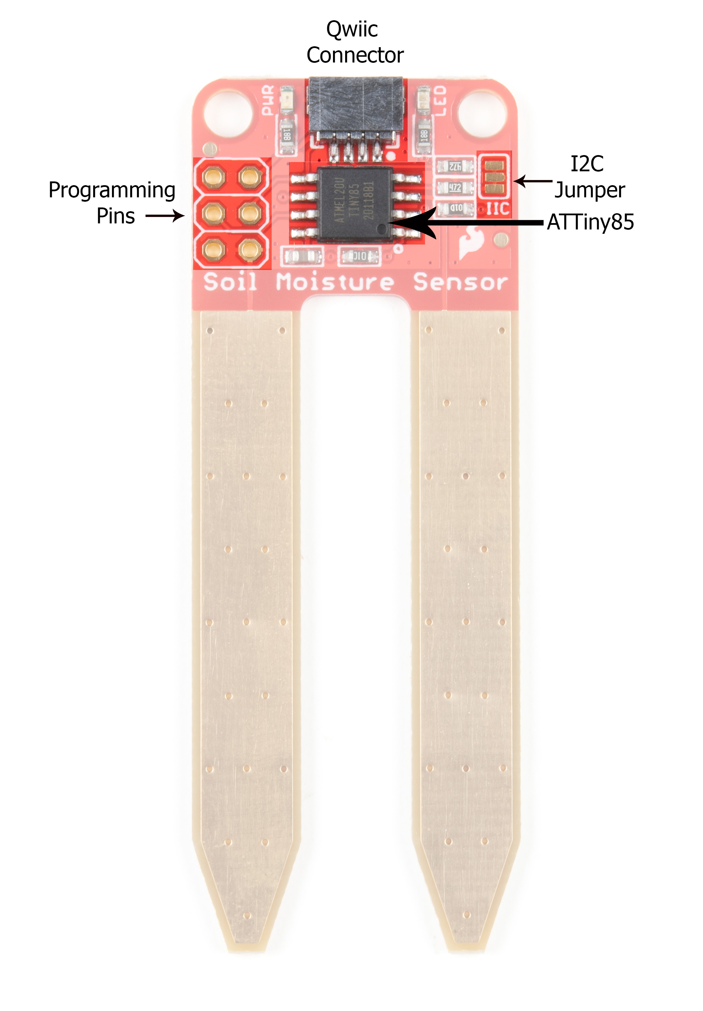
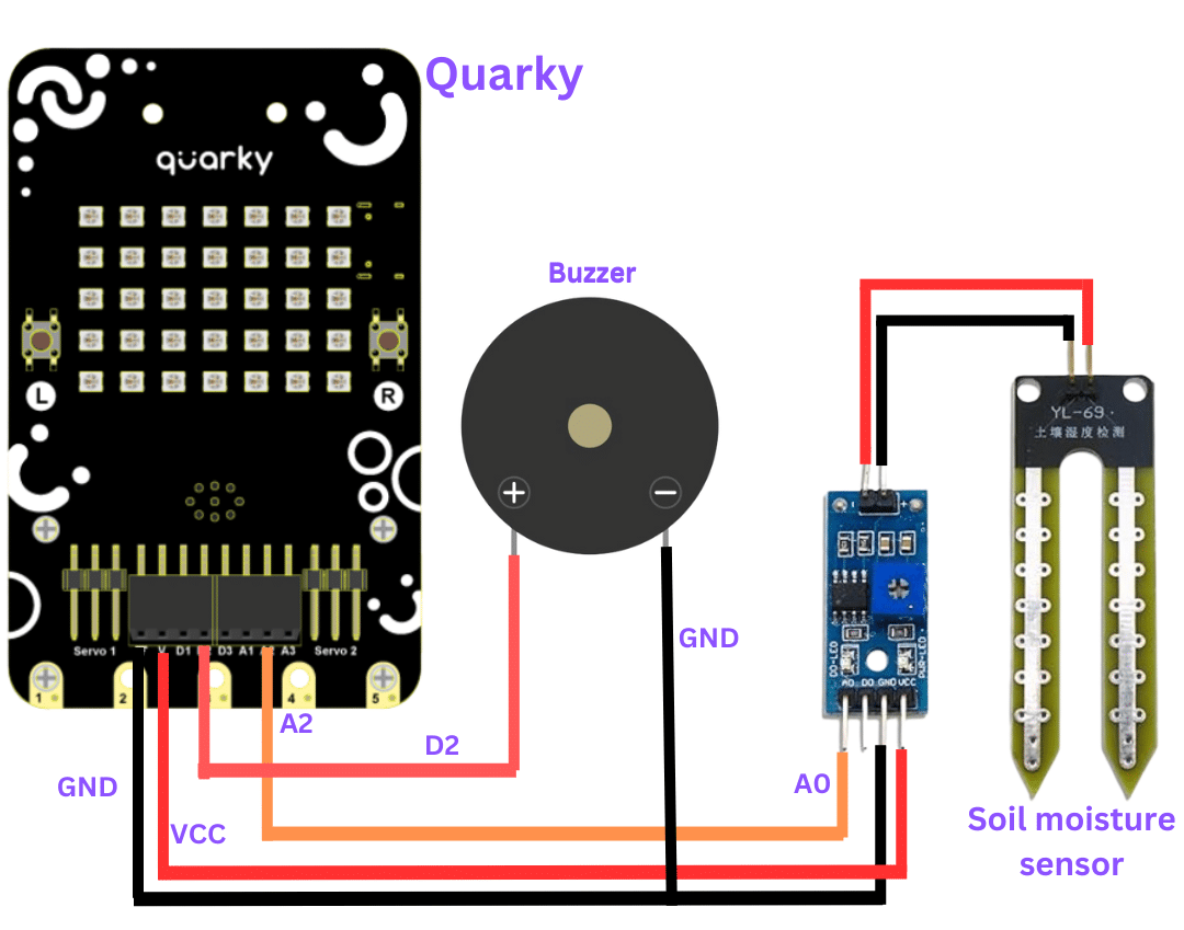
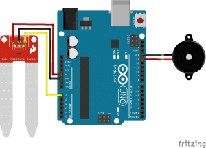
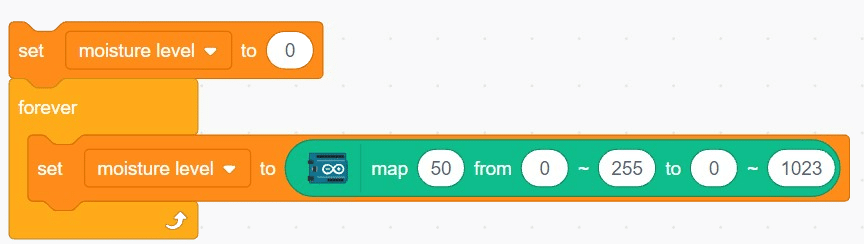
A soil moisture sensor is a valuable tool used to determine the moisture content in the soil, crucial for efficient gardening, farming, and agricultural practices. This analog sensor generates varying output values depending on the moisture level present in the soil. Typically, it operates as a two-pin circuit, with these pins responsible for powering up the sensor module. To obtain soil moisture readings, a voltage divider circuit is employed on the negative pin of the sensor, resulting in a signal pin that provides the moisture level data. Alternatively, some sensor modules come with a controller circuit that automatically converts the 2-pin connection into a 3-pin output, simplifying the process of accessing moisture values.
Below is a simple circuit diagram and code to get you started with monitoring soil moisture using an Arduino board. By following these steps, you can create your own moisture monitoring system with ease. Let’s begin!

With these steps, your script is complete, and you can now monitor the soil moisture effectively using the soil moisture sensor and Arduino board. Happy gardening and farming!
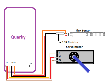
The flex sensor is an ingenious device employing carbon on a plastic strip to serve as a variable resistor. As the sensor bends in one direction, its resistance varies accordingly. The more it bends, the higher the resistance becomes. This unique property makes it an ideal choice for applications where detecting bending or flexing is necessary.
In this example, we will be interfacing a flex sensor with Quarky and based on the change in its resistance we’ll be controlling the movement of our servomotor.
Circuit Diagram


Output GIFs are need to be updated
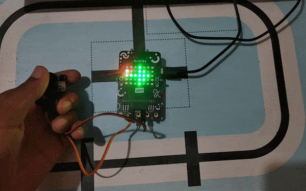
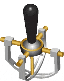
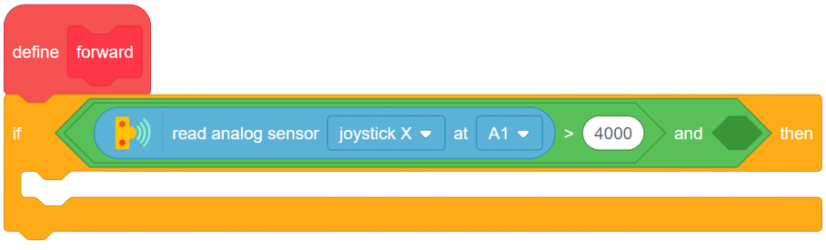
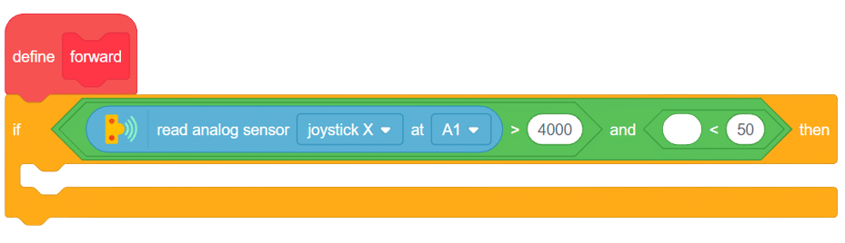
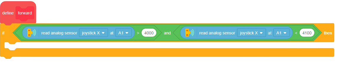
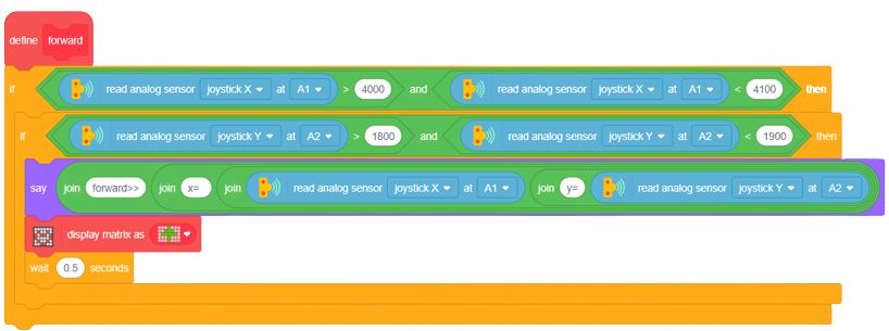
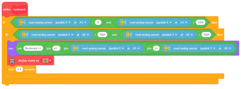
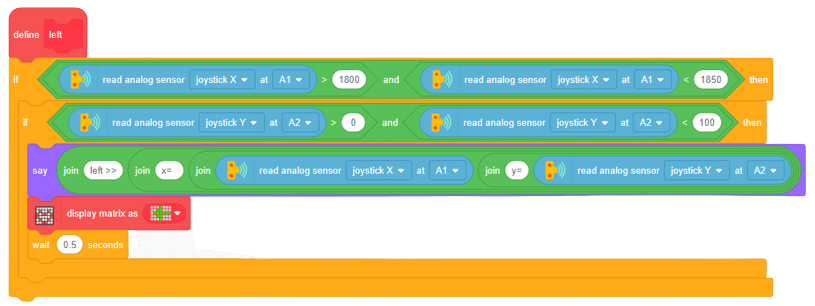
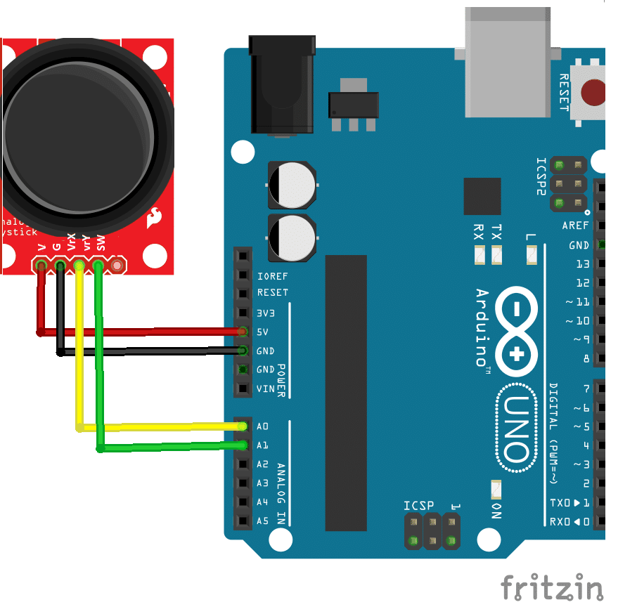
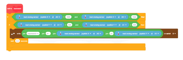
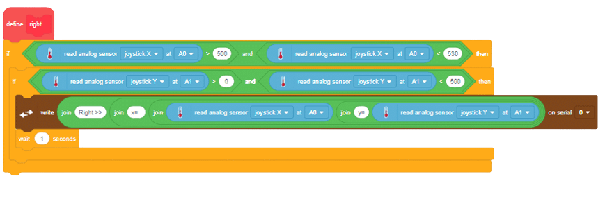
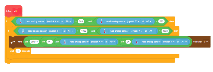
A joystick is an input device used to control the movement or actions of a computer, video game console, or other electronic device. In gaming, joysticks are often used to control the movement of characters or vehicles in a virtual environment. They provide analog input, meaning the degree of movement can vary based on how far the handle is pushed in a particular direction. In aviation and flight simulation, joysticks are commonly used to simulate the control of aircraft, providing pitch, roll, and yaw inputs. Some advanced joysticks also come with additional features such as throttle controls, programmable buttons, and force feedback to enhance the gaming or simulation experience. below is a simple animation of a joystick.
In this example, we’ll be interfacing a joystick with Quarky and try to find different directions for our robot by moving the joystick along the x and y axis let’s begin!!
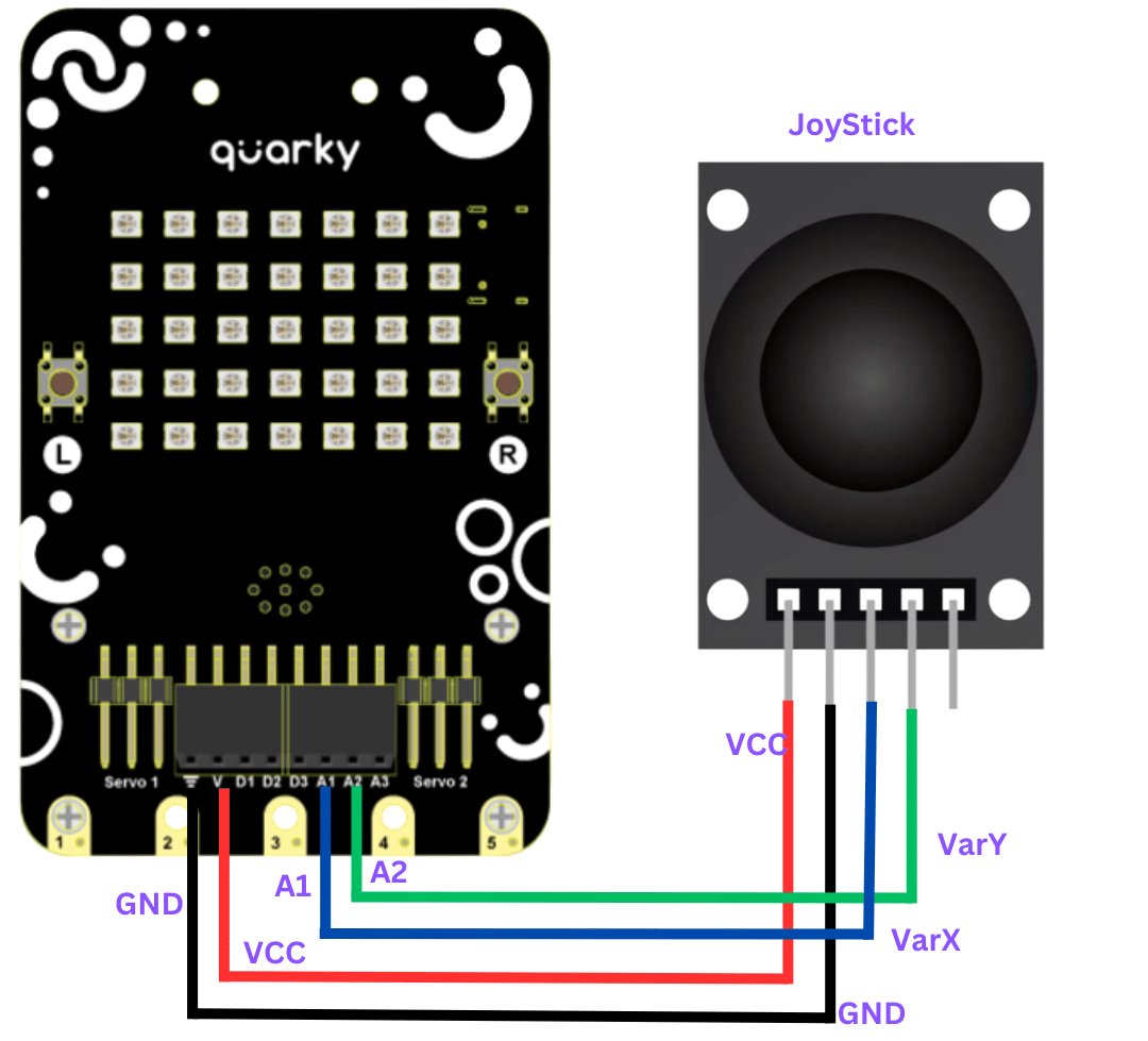
connection
JoyStick Quarky
GND GND
5V V
VarX A1
VarY A2
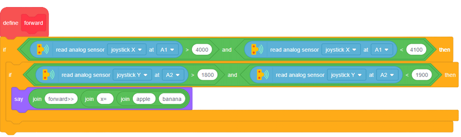
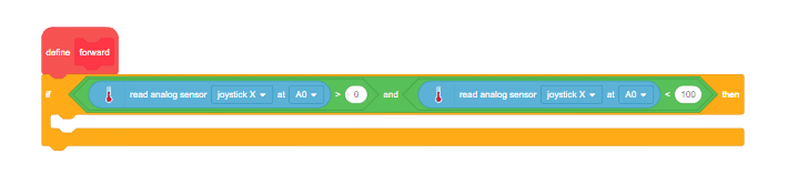
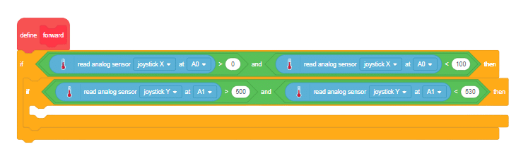
this is logic we will be using
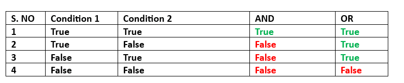
Remember that whenever we are moving the joystick in any direction, the value of both X and Y axis changes simultaneously, so we will be defining a range for both the X-axis and Y-axis so that when their values lie under this range our system must be able to decide the direction as forward,backward, left or right. based on the ranges and logic.
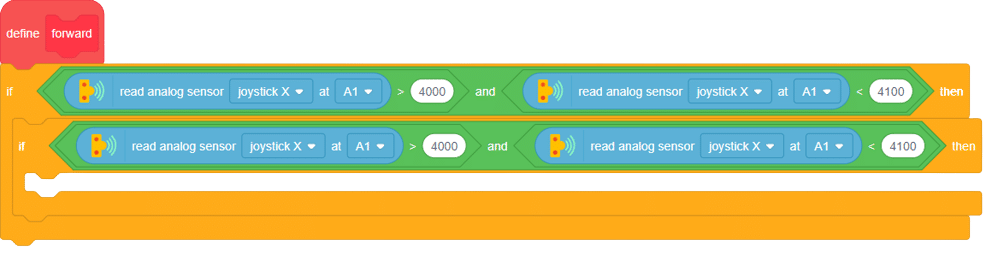
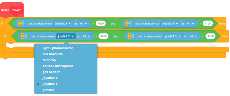
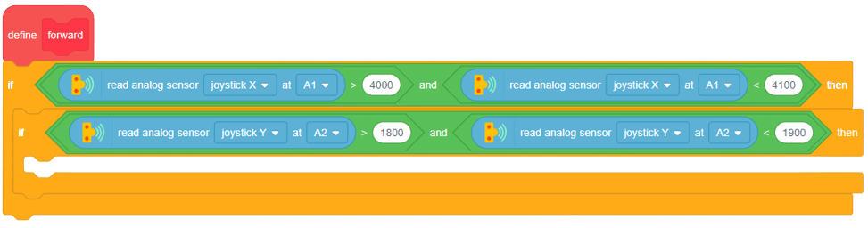
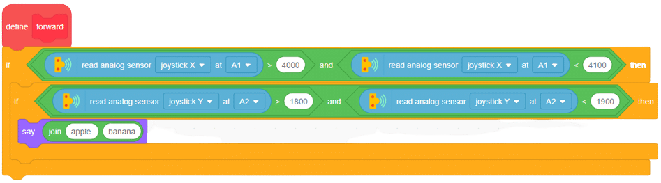
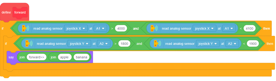
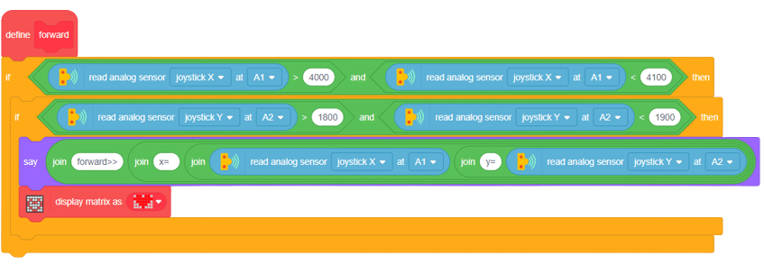
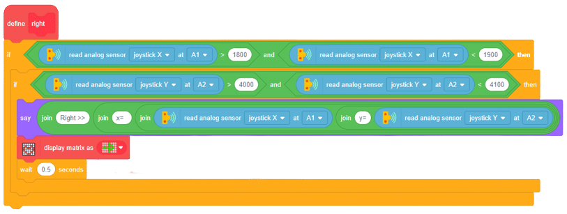


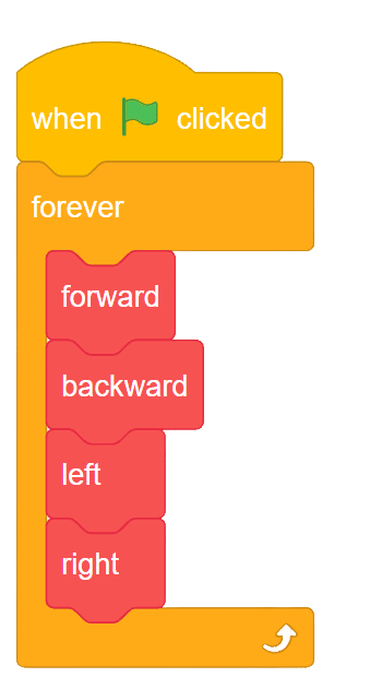
By following all the above steps, you will be able to control the robotic car in any direction you want.
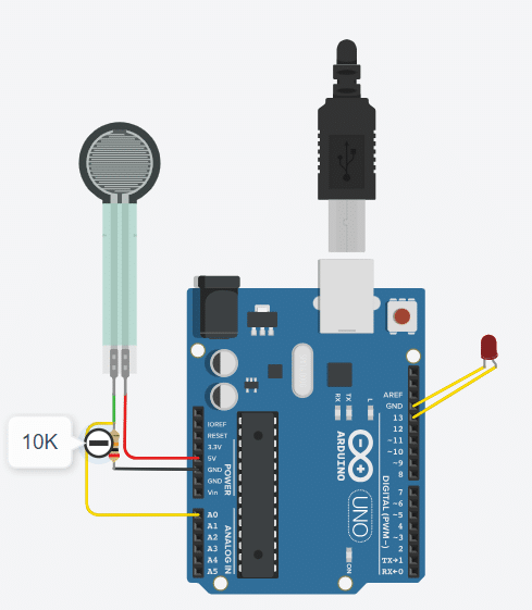
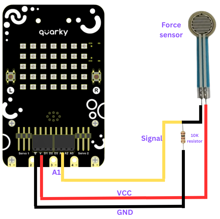
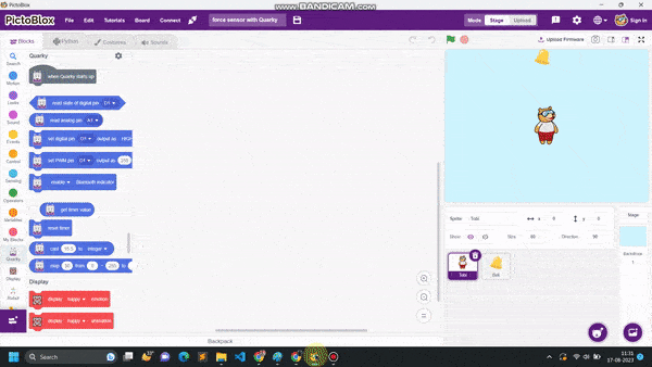
A force sensor, also known as a load cell or force transducer, is a device designed to measure the force or load applied to it. It’s used in various applications to quantify the magnitude of forces in different directions. Force sensors are utilized in fields such as engineering, manufacturing, robotics, healthcare, and more.

Joystick Is Basically Input Device That Will Be Used TO Control The Robotics And It Has Been Also Used In Gaming. The Joystick Are Different Types And Uses In Different Purposes. The Above Images Shows The Pins That Will Be Used For Interfacing With Hardware. We Know About The First Two Pin That Is Basic Pins Which Is Used In Every Hardware. That Is +5V And Another Is Ground. Another Three Pins Are Input And Output Pins. The VRx And VRy Are The Input Pin And SW Is The Output Pines Will Briefly Understand About The Interfacing Joystick With Arduino.
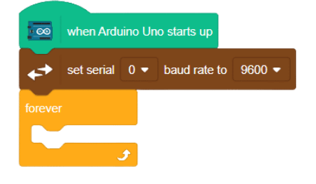
 click on communication extensions and drag “set serial () baud rate to () ” into the scripting area.
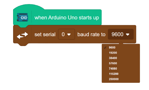
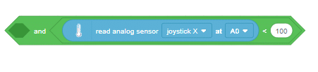
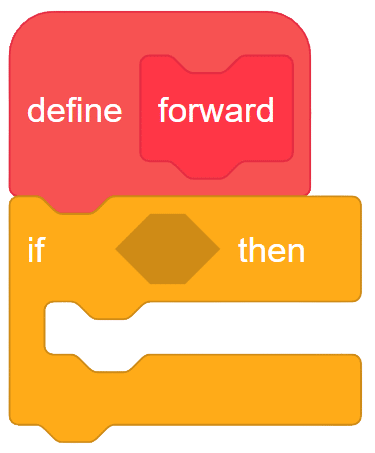
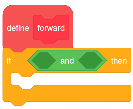
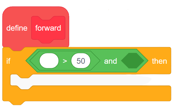
 Again from the operator palette drag less then operator and insert in second space if the AND operator.
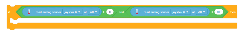

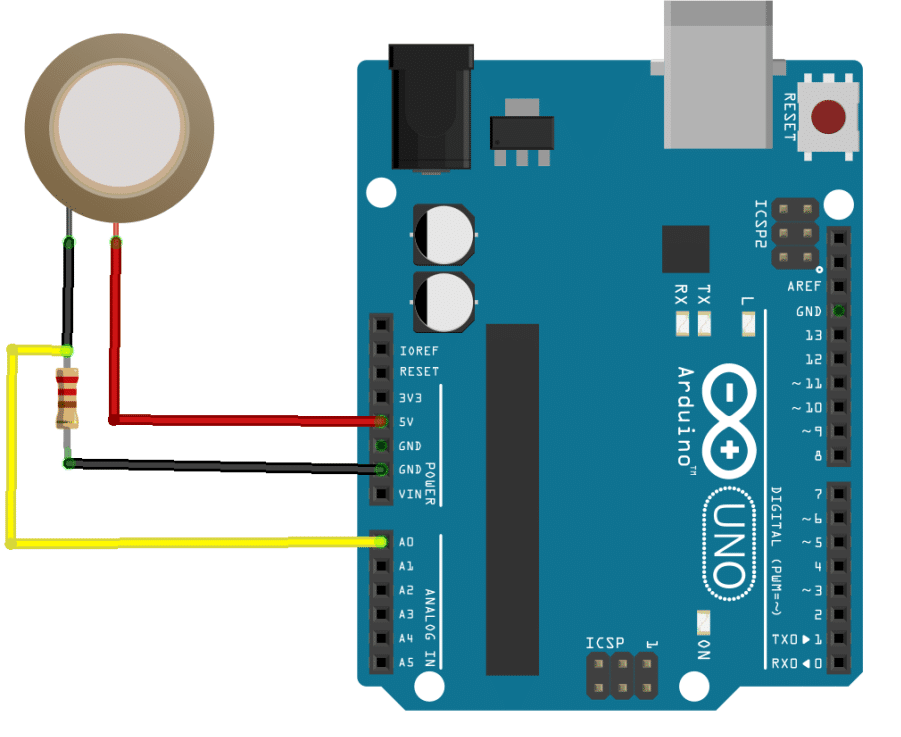
A piezoelectric sensor is a type of sensor that uses the piezoelectric effect to measure changes in pressure, acceleration, force, temperature, and other physical quantities. The piezoelectric effect is a phenomenon in which certain materials generate an electric charge in response to mechanical stress or deformation. This property makes piezoelectric sensors useful for a wide range of applications where accurate measurements of mechanical changes are required. Here’s how piezoelectric sensors work:


OUTPUT Gifs will be updated soon.
A piezoelectric sensor is a type of sensor that uses the piezoelectric effect to measure changes in pressure, acceleration, force, temperature, and other physical quantities. The piezoelectric effect is a phenomenon in which certain materials generate an electric charge in response to mechanical stress or deformation. This property makes piezoelectric sensors useful for a wide range of applications where accurate measurements of mechanical changes are required. Here’s how piezoelectric sensors work:
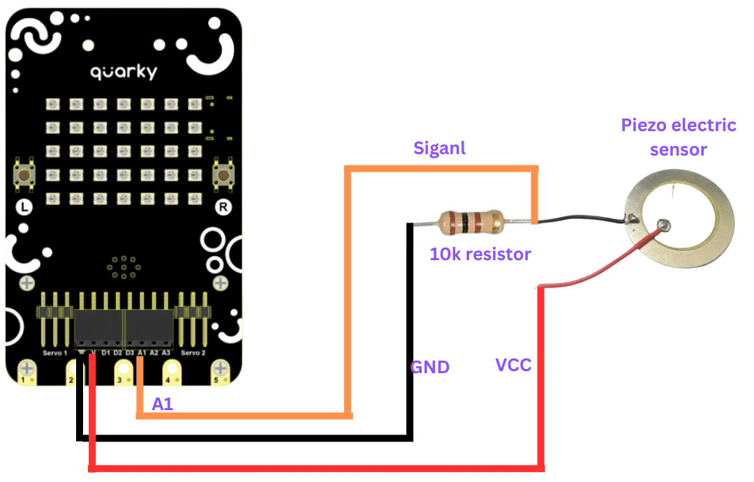
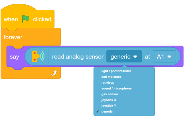
Now to read the different changes from the sensor, hit the sensor with your punch and you will see the change in sensor value shown by your sprite.
OUTPUT Gifs will be updated soon.
A force sensor, also known as a load cell or force transducer, is a device designed to measure the force or load applied to it. It’s used in various applications to quantify the magnitude of forces in different directions. Force sensors are utilized in fields such as engineering, manufacturing, robotics, healthcare, and more.

with this, your script is complete now.
Output Gif will be updated soon.
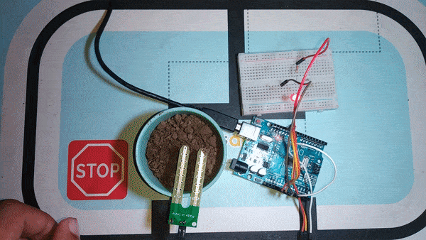
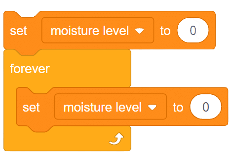
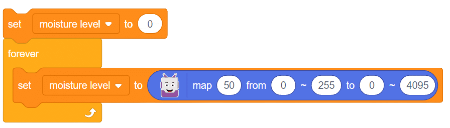
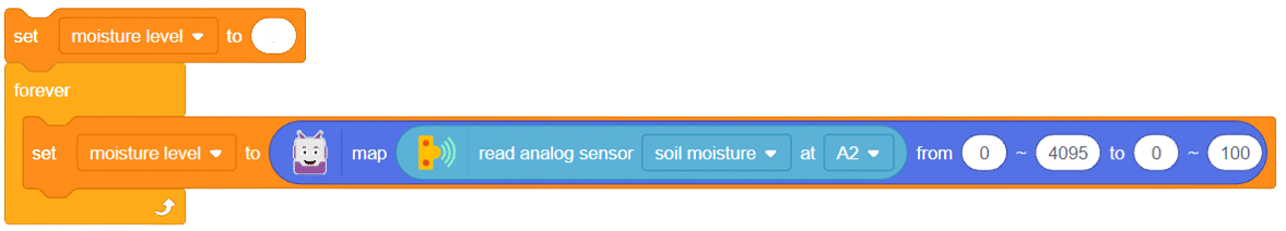
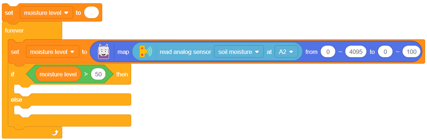
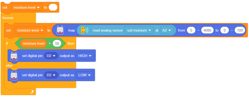
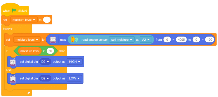
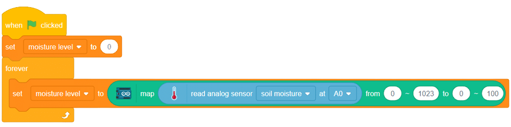
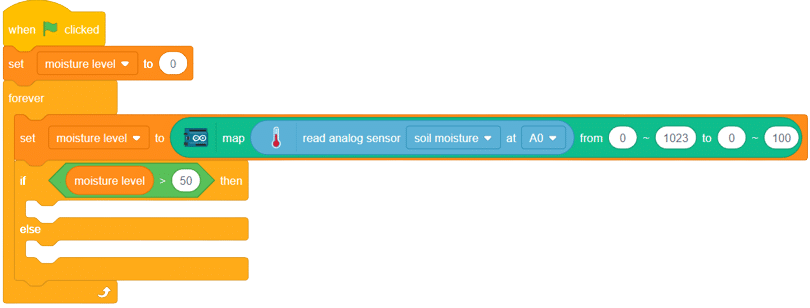
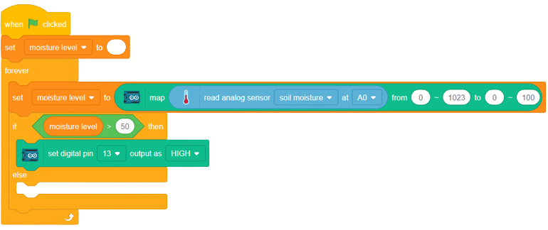
The soil moisture sensor is a valuable tool used to determine the moisture content in the soil, crucial for efficient gardening, farming, and agricultural practices. This analog sensor generates varying output values depending on the moisture level present in the soil. Typically, it operates as a two-pin circuit, with these pins responsible for powering up the sensor module. To obtain soil moisture readings, a voltage divider circuit is employed on the negative pin of the sensor, resulting in a signal pin that provides the moisture level data. Alternatively, some sensor modules come with a controller circuit that automatically converts the 2-pin connection into a 3-pin output, simplifying the process of accessing moisture values.
Below is a simple circuit diagram and code to get you started with monitoring soil moisture using an Arduino board. By following these steps, you can create your own moisture monitoring system with ease. Let’s begin!
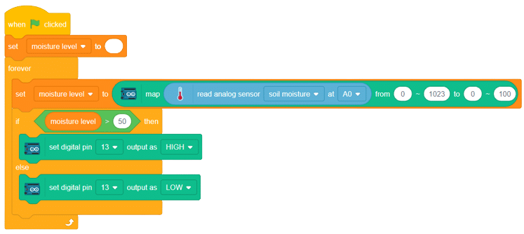
With these steps, your script is complete, and you can now monitor the soil moisture effectively using the soil moisture sensor and Arduino board. Happy gardening and farming!
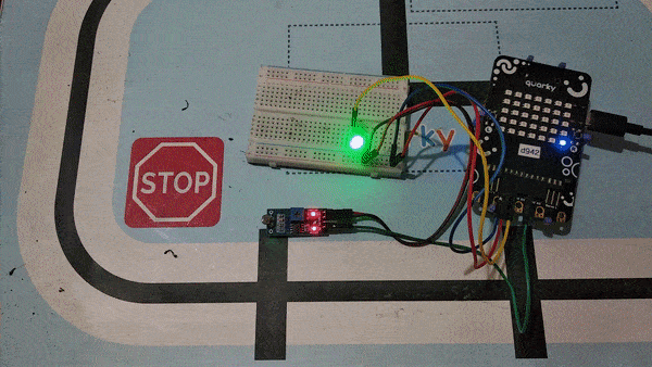
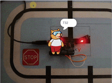
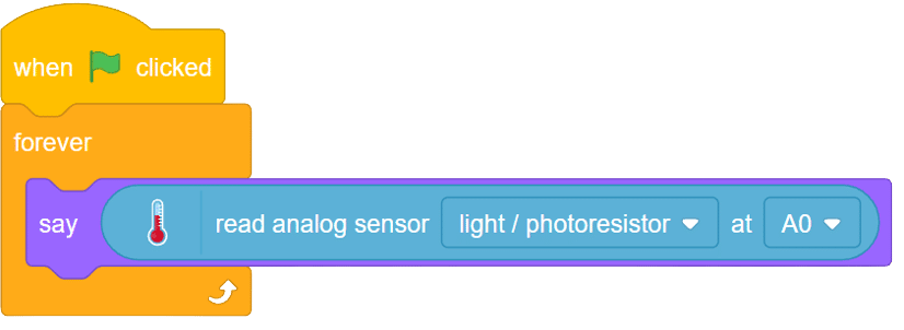
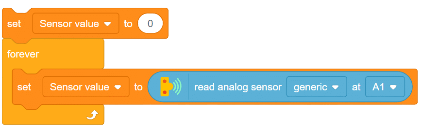
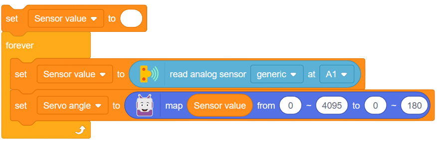
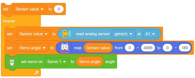
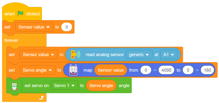
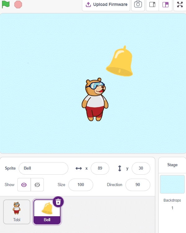
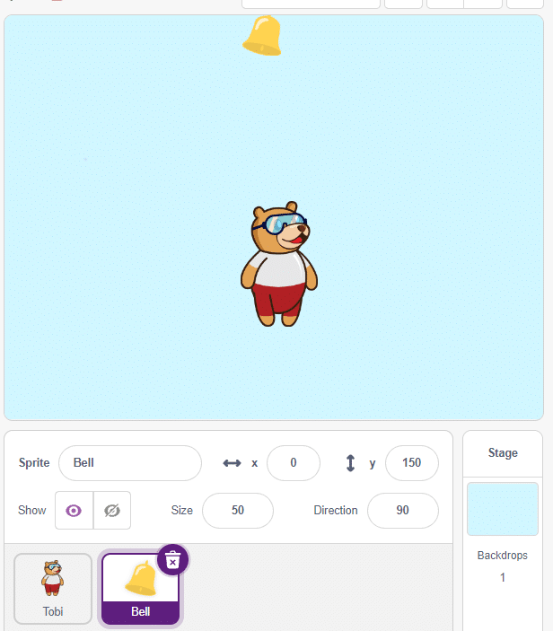
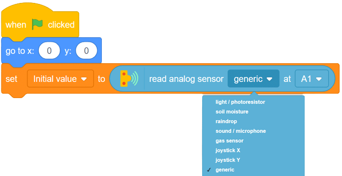
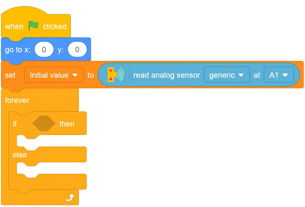
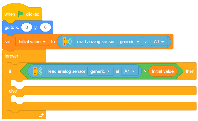
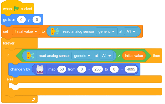
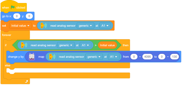
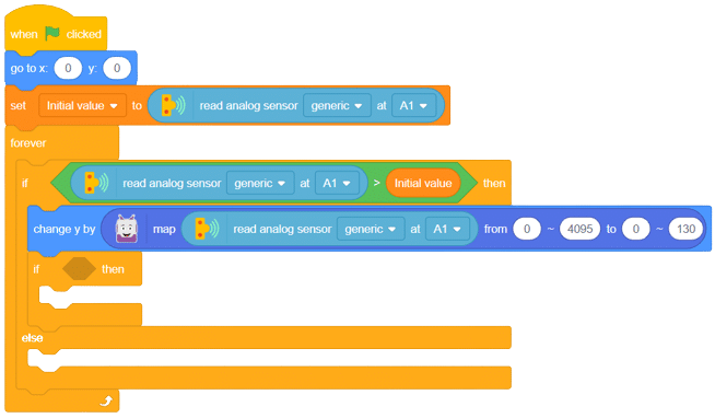
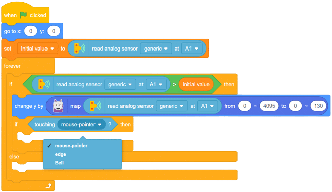
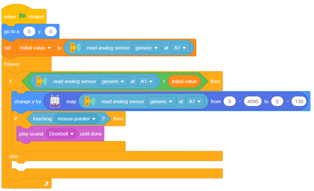
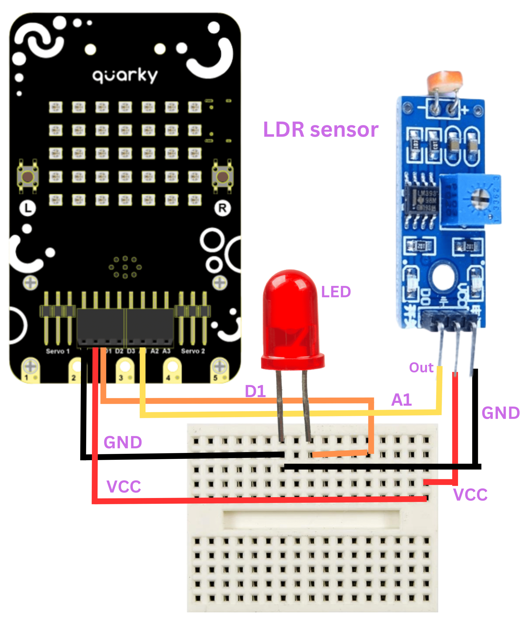
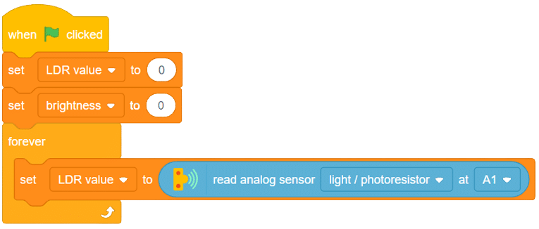
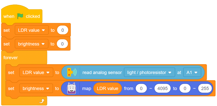
The LDR (Light Dependent Resistor) sensor is a renowned analog-type sensor that adapts its resistance according to surrounding light intensity. With its ability to fluctuate resistance based on light changes, the LDR plays a vital role in various light-sensing applications. Though typically designed as a two-pin sensor, it is also available as a three-pin module, offering enhanced features and versatility.
In this example, we embark on a fun activity using the LDR sensor and Quarky. Through this engaging experience, you will grasp essential concepts like analog and PWM signals, creating an exciting learning journey. So, let’s dive in and explore the wonders of LDR and Quarky together!
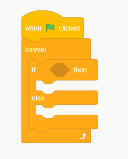
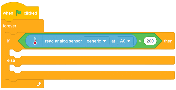
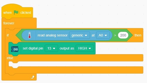
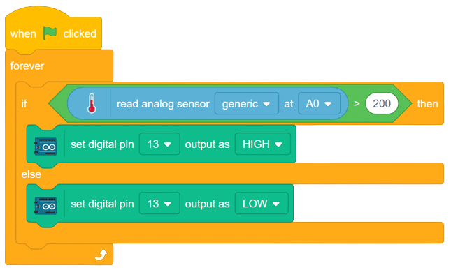
Follow these steps to implement the code using Pictoblox for Quarky and explore the behavior of the LDR sensor:

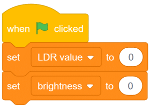
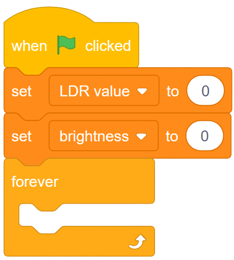
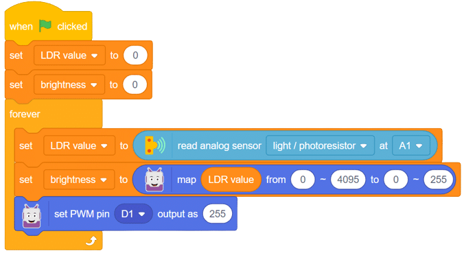
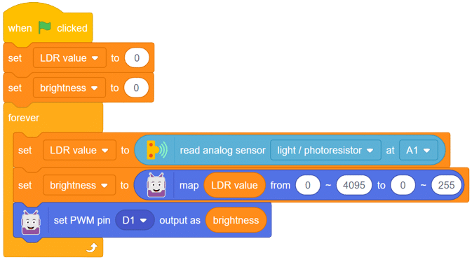
With these steps, your script is complete, and Quarky is ready to interact with the LDR sensor.
Through this exciting project, you have learned about the LDR sensor, its analog characteristics, and how Quarky can control an LED based on the light intensity sensed by the LDR. Delve deeper into the concepts of analog and PWM signals, making your robotics journey even more captivating with Quarky! Stay curious and keep exploring the endless possibilities!
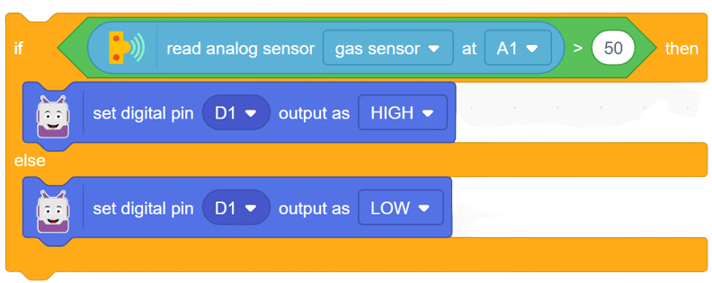
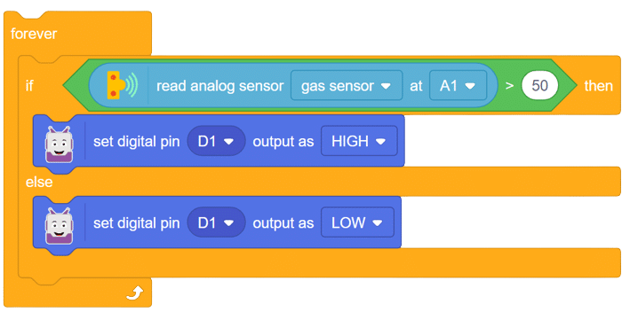
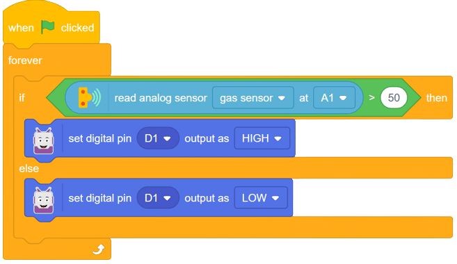
The MQ series of sensors comprises a range of gas detectors used to detect multiple gases like CO2, LPG, CO, and more. These sensors find applications in various scenarios, from detecting fire-induced smoke in buildings to detecting gas leaks, making them crucial for mining and other industries.
In this example, we will interface an MQ sensor with Quarky to specifically detect the presence of alcohol. Our objective is to detect alcohol levels and trigger an alarm if they exceed a certain limit. Let’s embark on this exciting journey of gas detection with Quarky!
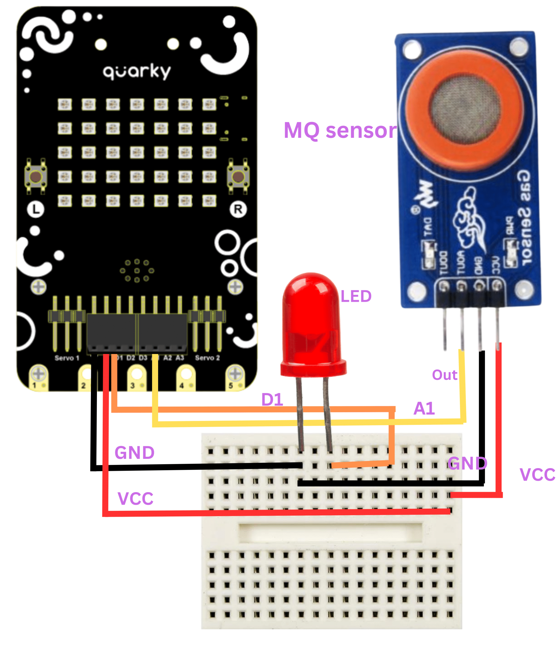
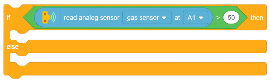
With this exciting project, you have learned how to interface an MQ sensor with Quarky to detect alcohol gas levels. Explore the diverse applications of MQ sensors, from detecting smoke in buildings to monitoring gas leaks in industrial settings. Create your own gas detection system with Quarky, and unleash the potential of gas sensing technology! Keep experimenting, and the world of robotics and AI will become your playground!
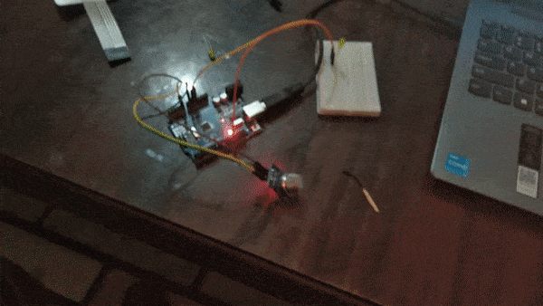
Output gifs are need to be updated.
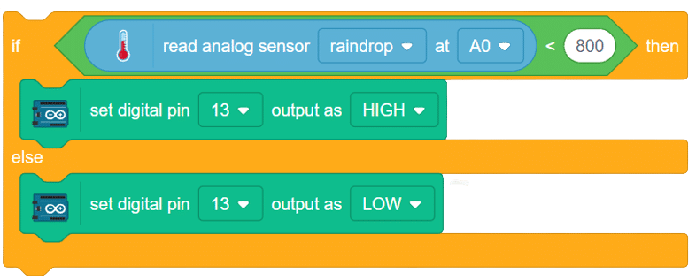
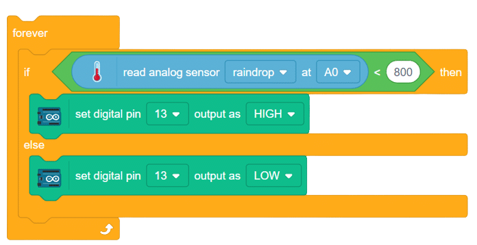
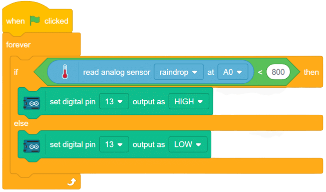
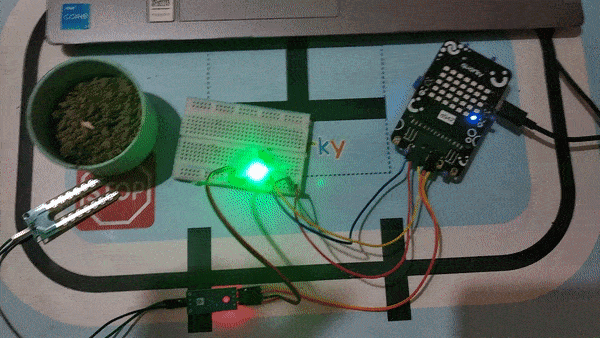
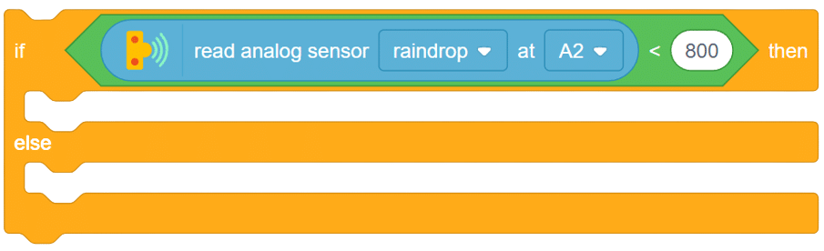
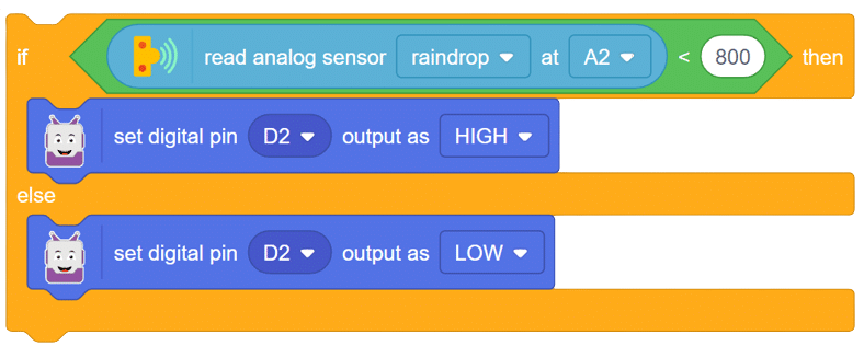
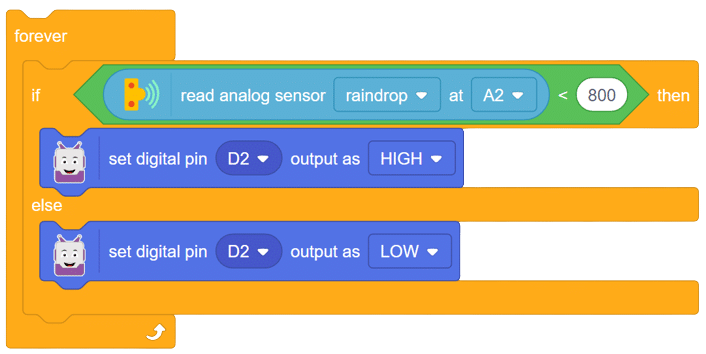
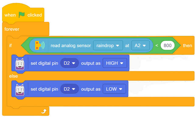
The raindrop sensor is an analog-type sensor that effectively measures changes in resistance when it encounters water. This property makes it an ideal choice for detecting rain and water presence in various applications. While typically designed with two pins, there are also versions available with a controller module, effectively converting it into a three-pin sensor for enhanced functionality.
To set up the raindrop sensor circuit, make the following connections:
A joystick is an input device used to control the movement or actions of a computer, video game console, or other electronic device. In gaming, joysticks are often used to control the movement of characters or vehicles in a virtual environment. They provide analog input, meaning the degree of movement can vary based on how far the handle is pushed in a particular direction. In aviation and flight simulation, joysticks are commonly used to simulate the control of aircraft, providing pitch, roll, and yaw inputs. Some advanced joysticks also come with additional features such as throttle controls, programmable buttons, and force feedback to enhance the gaming or simulation experience. below is a simple animation of a joystick.
In this example, we’ll be interfacing a joystick with Quarky and try to read the values of the joystick along the x and y axis let’s begin!!
connection
JoyStick Quarky
GND GND
5V V
VarX A1
VarY A2

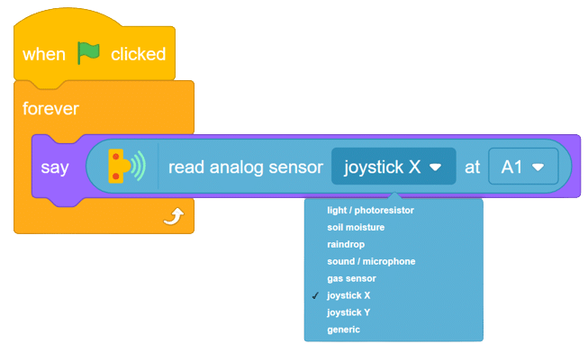
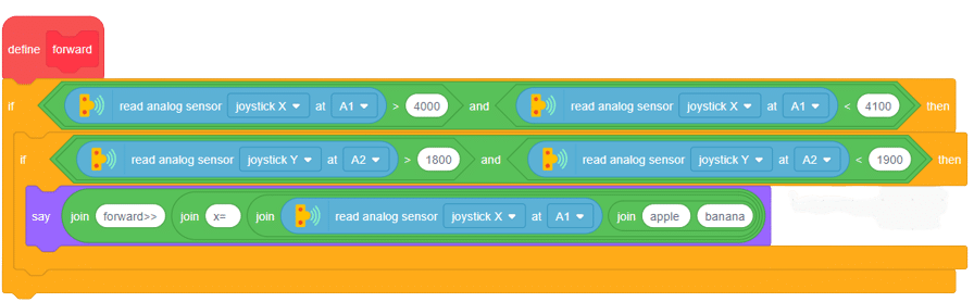
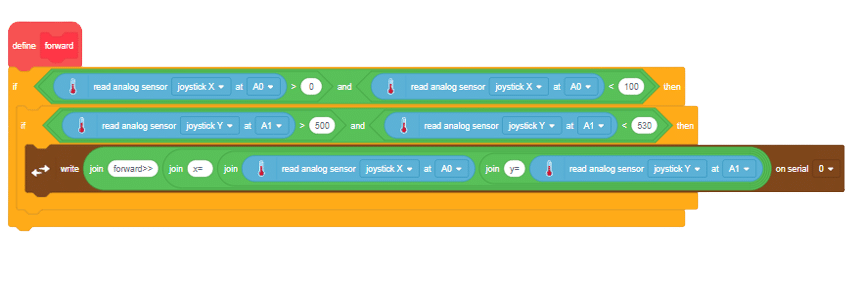
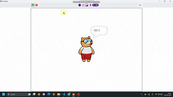
Now run the code, with this simple script, you will be able to read the value of the joystick along for X-axis in forward, backward, left, and right. with these values you will be able to set the logic on different values for fixing the direction as forward, backward, etc. do same for finding values for Y-axis.
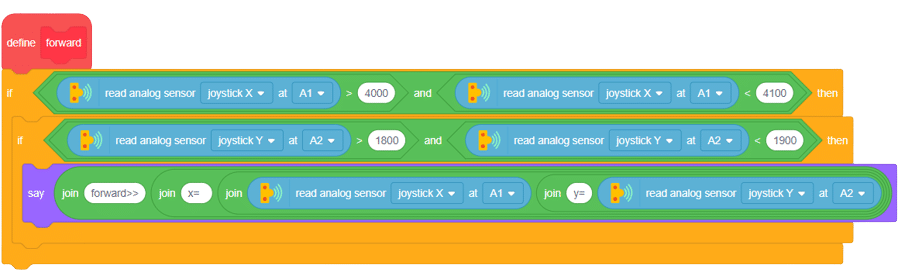
Task for you.
Try to print the value of both the axis together