

Intellio Advance Sensors Extension
Extension Description
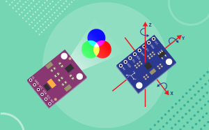
The Quarky Advance Sensors Extension allows you to easily work with a wide range of external sensors and displays connected to Quarky Intellio. This extension enables real-world data collection, sensor monitoring, and interactive displays — all controlled through simple blocks in PictoBlox.
-
Available in: Block Coding, Python Coding
-
Mode: Stage Mode
-
WiFi Required: Yes
-
Compatible Hardware in Block Coding: Quarky Intellio
-
Compatible Hardware in Python: Quarky Intellio
-
Object Declaration in Python: NA
Introduction
Quarky Intellio is a powerful AI learning module, and the Advance Sensors Extension expands its capabilities by connecting external sensors and displays. With this extension, you can:
- Monitor health data using pulse/heart rate sensors
- Detect colors and proximity with color sensors
- Track motion and orientation with accelerometers and gyroscopes
- Measure environmental conditions (temperature, pressure, altitude, humidity, weather patterns)
- Detect obstacles with distance and LiDAR sensors
- Monitor power and current consumption with current/power sensors
- Display information on OLED and LCD screens
- Measure water flow rate and pH levels
- Track GPS location with a NEO-6M GPS module
This extension is perfect for building projects related to robotics, environmental monitoring, health tracking, obstacle avoidance, and data visualization. By using the Advance Sensors Extension, you learn how sensors collect data from the physical world and how PictoBlox processes and displays that information in real time.
Connecting Quarky Intellio with PictoBlox
Let’s begin by first connecting Quarky Intellio to PictoBlox. Follow the step-by-step instructions in the Quarky Intellio Connection Guide to establish the connection.
Read More
PictoBlox Blocks
Initialises the NEO-6M GPS module through UART serial communication. Connect the TX pin of Quarky to the RX pin of the GPS module, and the RX pin of Quarky to the TX pin of the GPS module. The module begins searching for satellites after initialisation. A cold start may take 30 seconds to several minutes to obtain a satellite fix. Keep the module in an area with a clear view of the sky.
Initialises the INA219 current and power monitoring sensor through I2C communication. The sensor checks I2C address 0x40 first and falls back to 0x41 if necessary. It also calibrates the sensor for an expected maximum current of 400 mA with a 0.1 Ω shunt resistor, as specified in the supplied configuration.
Initialises the YDLIDAR X2 laser scanner through UART communication using the specified RX pin. Connect the LiDAR TX pin to Quarky’s RX pin; a Quarky TX connection is not required for receiving scan data. Connect the LiDAR M_CTRL pin to 3.3 V to keep the scanning motor running continuously.
Allow approximately three seconds for the motor to spin up before reading distance data. This block is available in Upload Mode only.
Recalibrates the INA219 sensor for a different maximum expected current without reinitialising it.
Available ranges:
0.4 A: Up to 400 mA, with the highest accuracy for this configuration.
1.0 A: Up to 1 A.
2.0 A: Up to 2 A.
3.2 A: Up to 3.2 A.
Use this block when the expected current exceeds the current calibration range. Ensure the selected range is appropriate for the sensor hardware and circuit.
All articles loaded
No more articles to load
Table of Contents