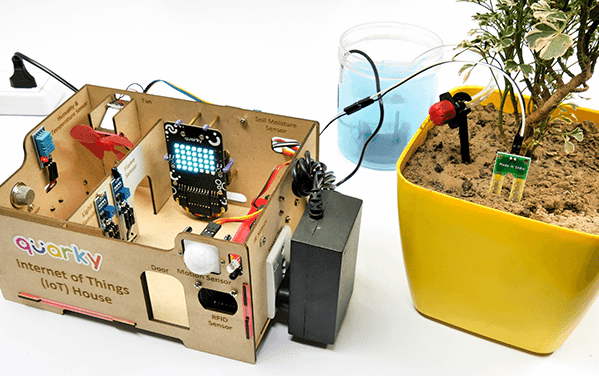
In this example, we will look into the basics of a Drip Irrigation System using the IoT House. With IoT House, you get 2 plant drip irrigation raw equipment.
Drip Irrigation
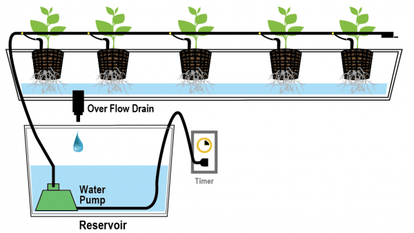
The drip irrigation system is a type of micro-irrigation of soil that has the potential to save water and nutrients by allowing water to drip slowly to the roots of plants. This leads to the wise use of water and also makes water reach the roots of plants and minimize evaporation. Drip irrigation systems distribute water through a network of valves, pipes, tubing, and emitters. Its efficiency depends on how well the system is designed, installed, maintained, and operated. A simple drip irrigation system is shown below in the figure.
Drip Irrigation Kit
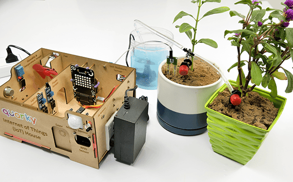
In this project, we will be using an IoT House Drip irrigation kit. This kit consists of various components out of which the following are required in our project
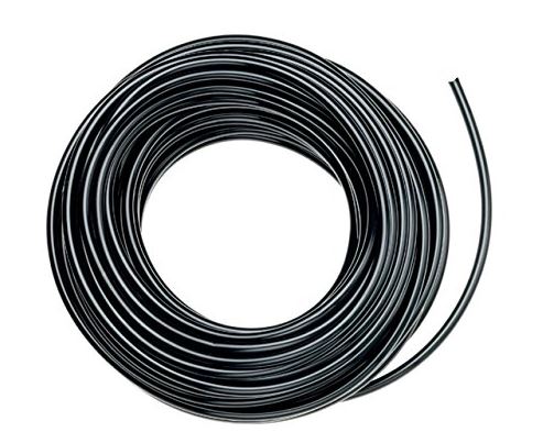
- A feeder line pipe is used to transfer water from the water tank source to the drip irrigation system. It is also used to connect the T-connectors to make different connections.
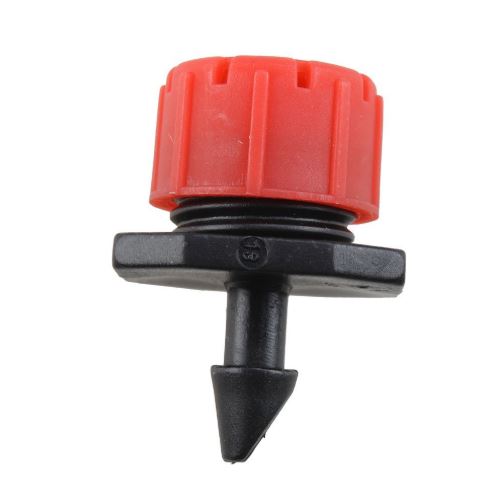
- A drip emitter is a small piece used to water the plant drop by drop. It is connected to the T connector with the help of a feeder line pipe of around(2.5 cm as per our requirement).
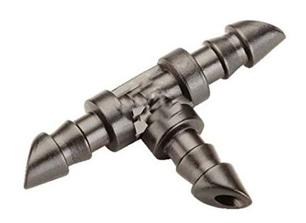
- A T connector is a T-shaped piece of plastic that connects one drip emitter to the adjacent drip emitter with the help of a feeder line pipe.
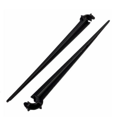
- Emitter stakes are stands with a curve at the top and pointed at another end. It will help to provide stability to the feeder line pipe drip emitter connections.
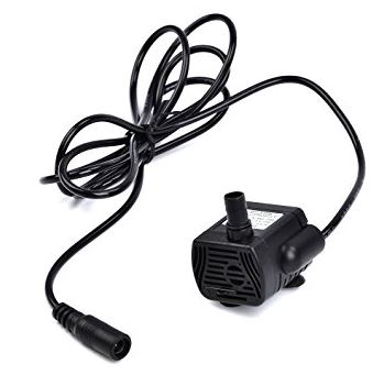
- A 12V,3W Water pump is connected at one end of the feeder pipeline. The male end of the water pump is connected female dc connector.
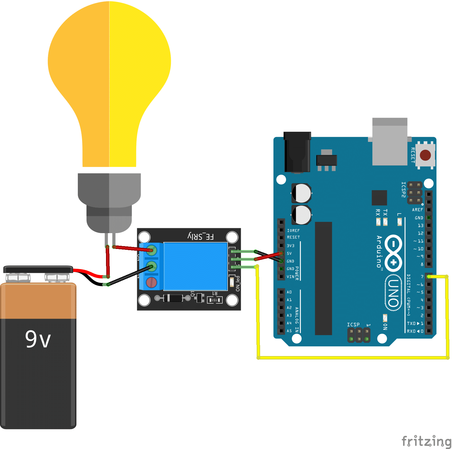
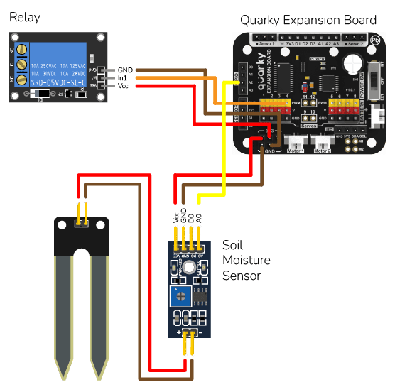
Circuit
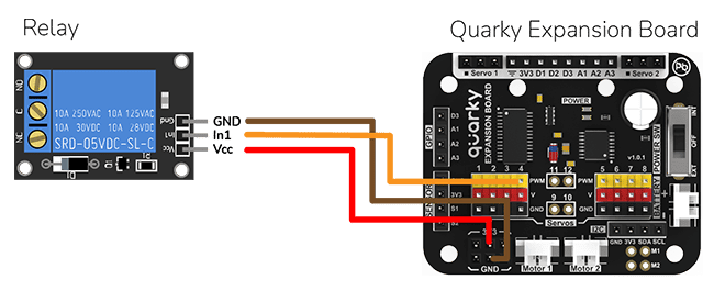
The Water Pump Connected to the Relay: The water pump is controlled by the smart switch of the IoT house which has a relay controlling the state. If the relay is ON, the smart switch gets ON, turning on the water pump. The relay has the following connections:
- GND Pin connected to GND of the Quarky Expansion Board.
- VCC Pin connected to VCC of the Quarky Expansion Board.
- Signal Pin connected to Servo 4 of the Quarky Expansion Board.
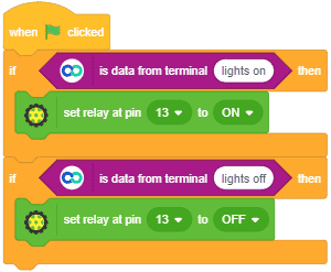
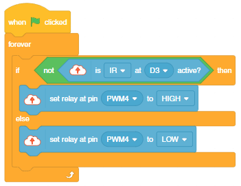
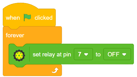
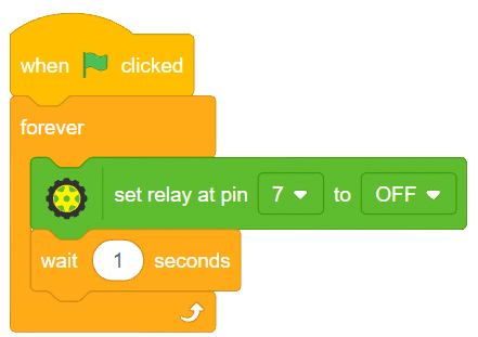
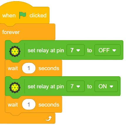
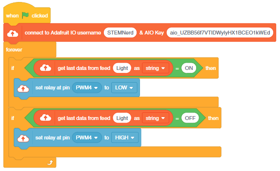
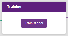
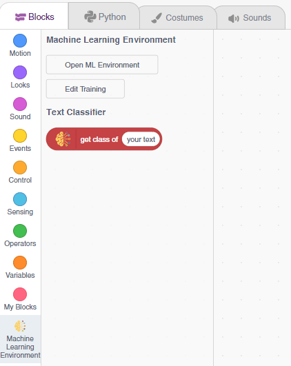
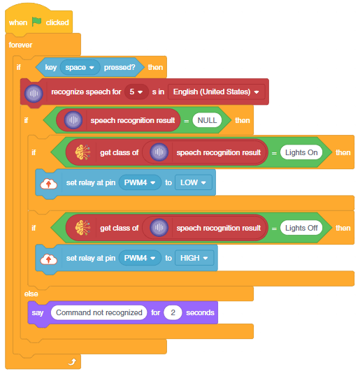
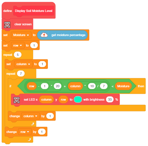
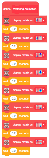
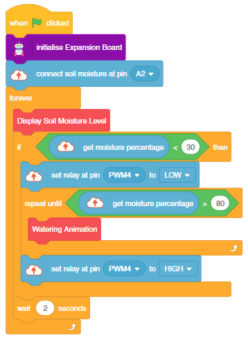
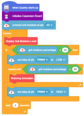
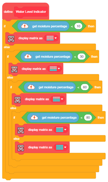
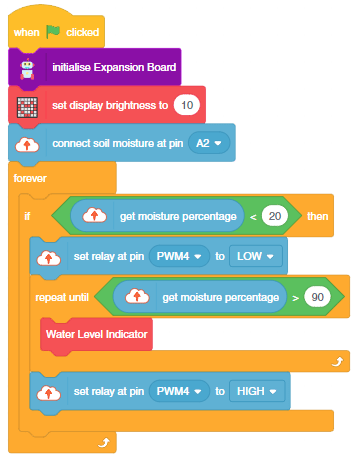
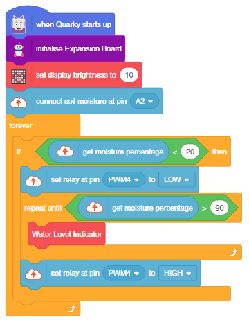
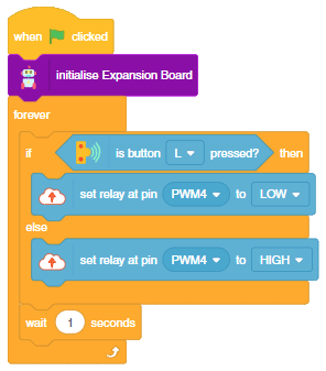
Script
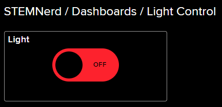
The pump will turn ON when the L button of the Quarky is pressed.
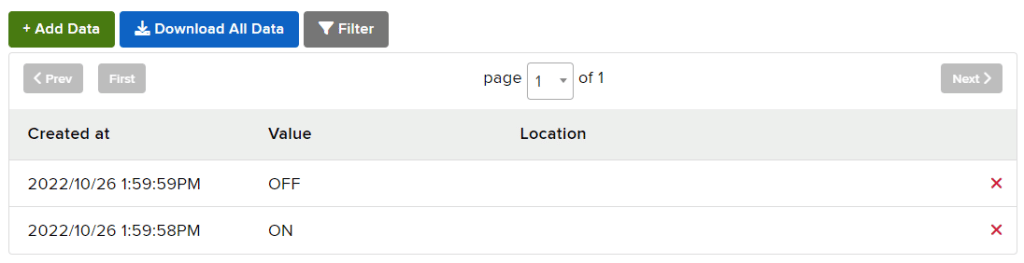
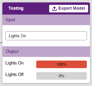
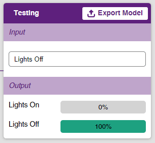
Output