
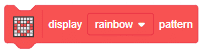


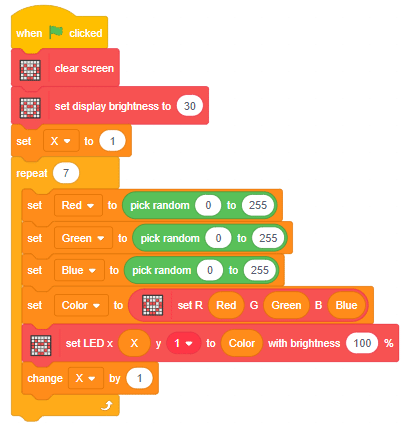
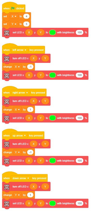
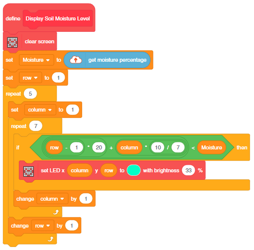
The block changes the color of the particular RGB LED of Quarky.
The block has the following inputs:
- x position of the LED you want to control
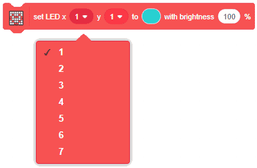
- y position of the LED you want to control
- the color you want o display
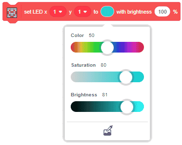
- the brightness of the LED
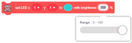

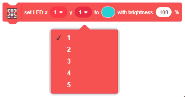
The block changes the color of the particular RGB LED of Quarky.
The block has the following inputs:


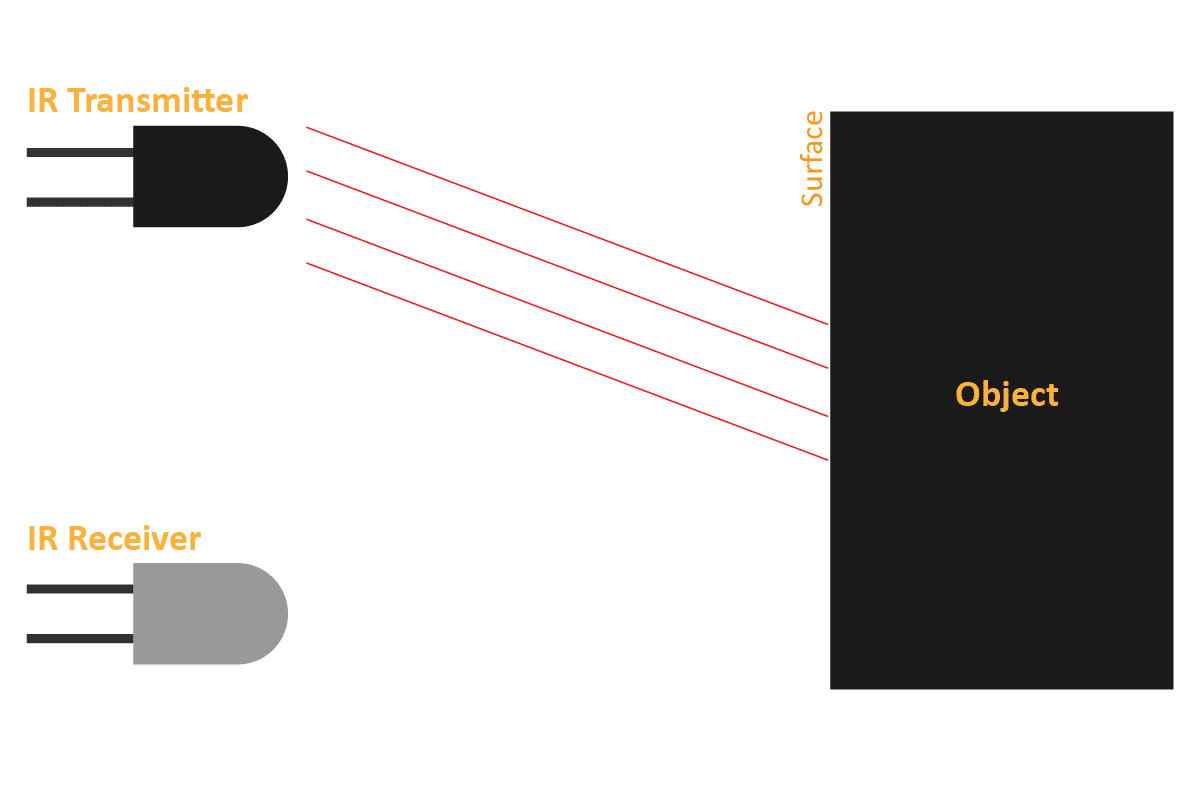
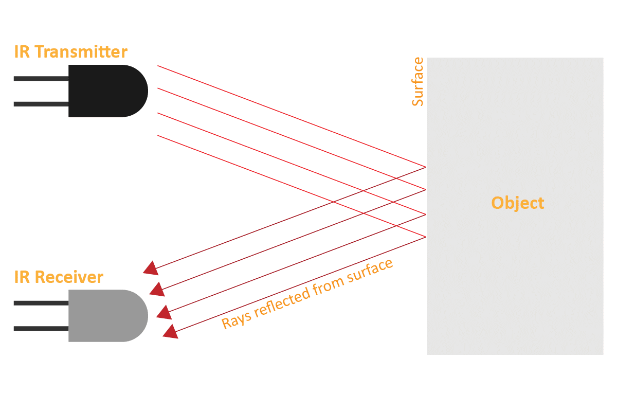
An IR sensor consists of 2 LEDs: one which transmits the IR light and one which receives the IR light. When the IR rays are transmitted, they bounce from the nearest surface and get back to the receiver LED. That’s how an IR sensor detects an object.
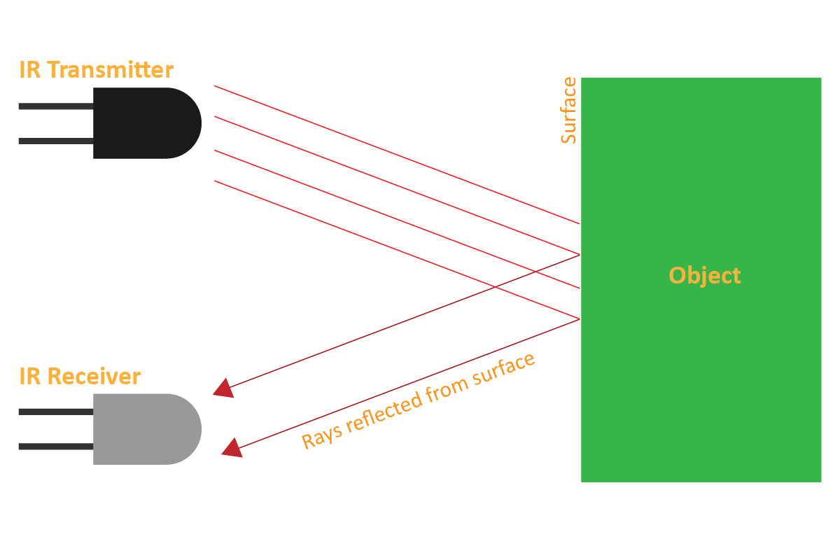
But to detect colors, we depend on the number of rays the surface reflects:
We can get the sensor values in PictoBlox and based on that value we can estimate whether the surface is black or white.
We will call the threshold value above which the sensor detects the black line. If the sensor value is less than the threshold, it means that the sensor hasn’t detected the line yet.

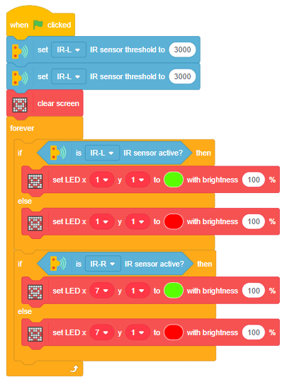
Now, run the script by clicking the green flag and bringing the black line of the track close to the IR sensor. One of the following three conditions will happen:
Now modify the script to add the detection value for the right IR sensor.
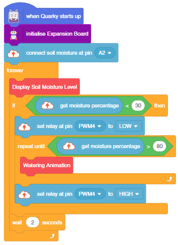
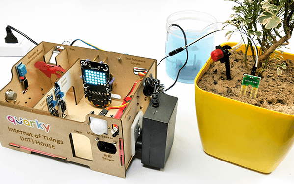
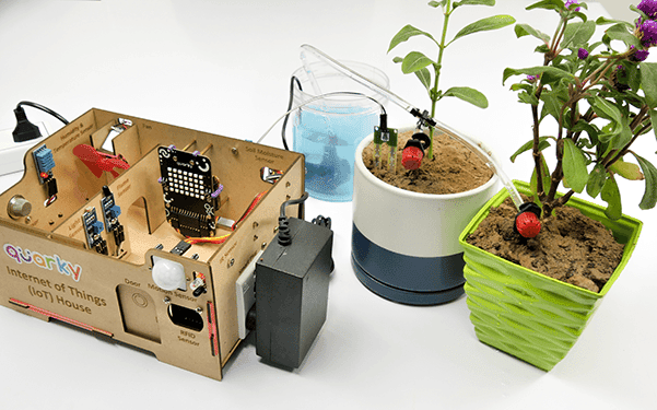
This example demonstrates how to use the Soil Moisture sensor to detect the moisture in the soil and water the plant using the drip system. The system will water the plant when the moisture of the soil is low.
The following tutorials cover how to make the Drip Irrigation System:
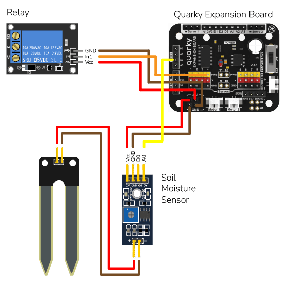
We are using 2 devices in this project:

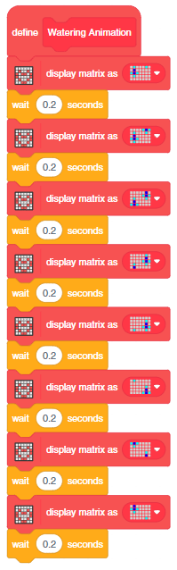
The project has 3 scripts:
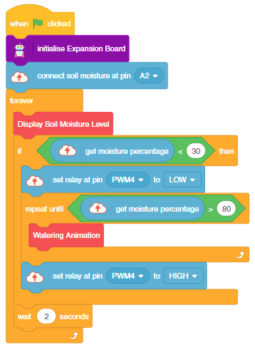
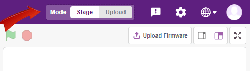
You can also make the script work independently of PictoBlox using the Upload Mode. For that switch to upload mode and replace the when green flag clicked block with when Quarky starts up the block.