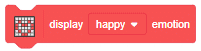

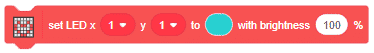


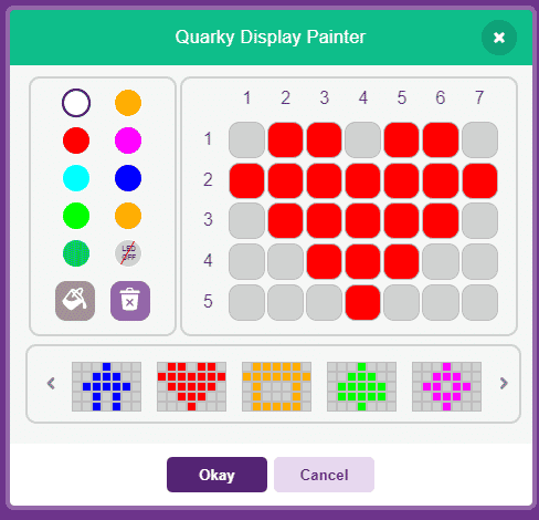
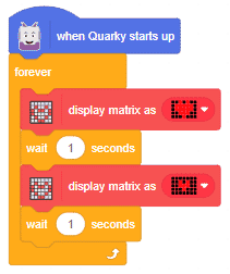
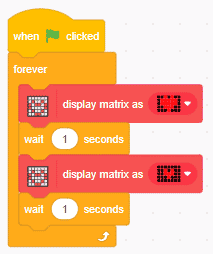
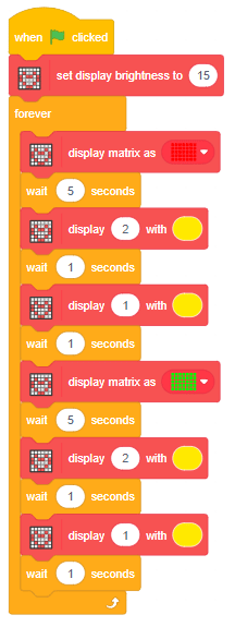
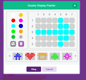
The block is used to create custom patterns on the RGB LED display of Quarky.
The pattern can be customized with the Quarky Display Painter window.

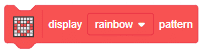
The block is used to create custom patterns on the RGB LED display of Quarky.
The pattern can be customized with the Quarky Display Painter window.

# This python code is generated by PictoBlox

from quarky import *
# This python code is generated by PictoBlox

# imported modules
import time


while True:
	quarky.drawpattern("jjbjbjjjbbbbbjjbbbbbjjjbbbjjjjjbjjj")
	time.sleep(1)
	quarky.drawpattern("jjjjjjjjjbjbjjjjbbbjjjjjbjjjjjjjjjj")
	time.sleep(1)


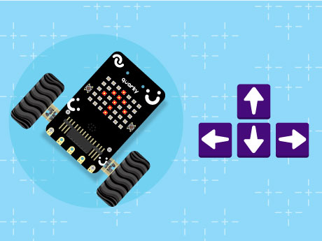
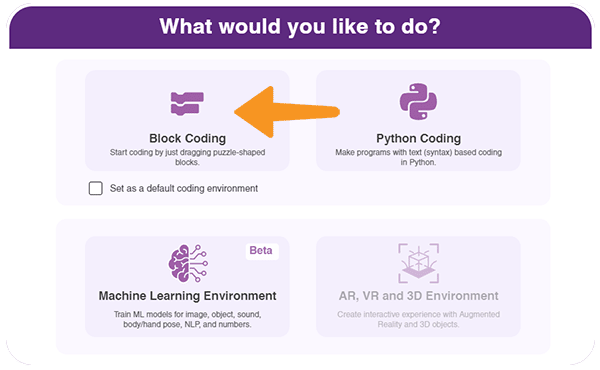
Have you ever wanted to control a robot using your computer keyboard — just like the robots used in automation labs, smart factories, and robotics competitions? In this fun and beginner-friendly robotics project, we will program the Quarky robot to move in different directions using the arrow keys in PictoBlox’s Block Coding mode. No complicated coding knowledge is required, just simple drag-and-drop blocks to bring your robot to life!
Using Quarky and PictoBlox, we will create a block-coded script that allows the robot to move forward, backward, left, and right while also displaying direction symbols on the RGB LED matrix Display for interactive visual feedback. The robot will even stop automatically when no key is pressed, making the control system smooth and user-friendly. This project is a great introduction to robotics control systems, human-machine interaction, and real-time input handling using block coding!
4. Quarky plays a confirmation sound on connecting. Voila! Your Quarky is now connected to PictoBlox!
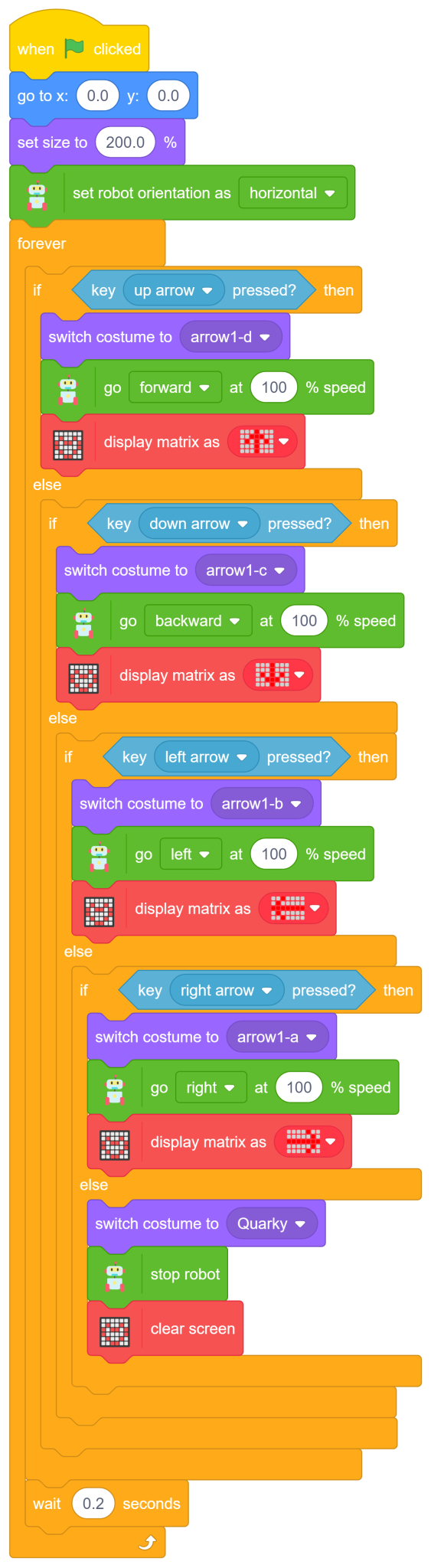
The first conditional checks whether the up arrow key on the keyboard is pressed. If true, Quarky moves forward at full speed while displaying a forward direction symbol on the LED matrix.
![]()
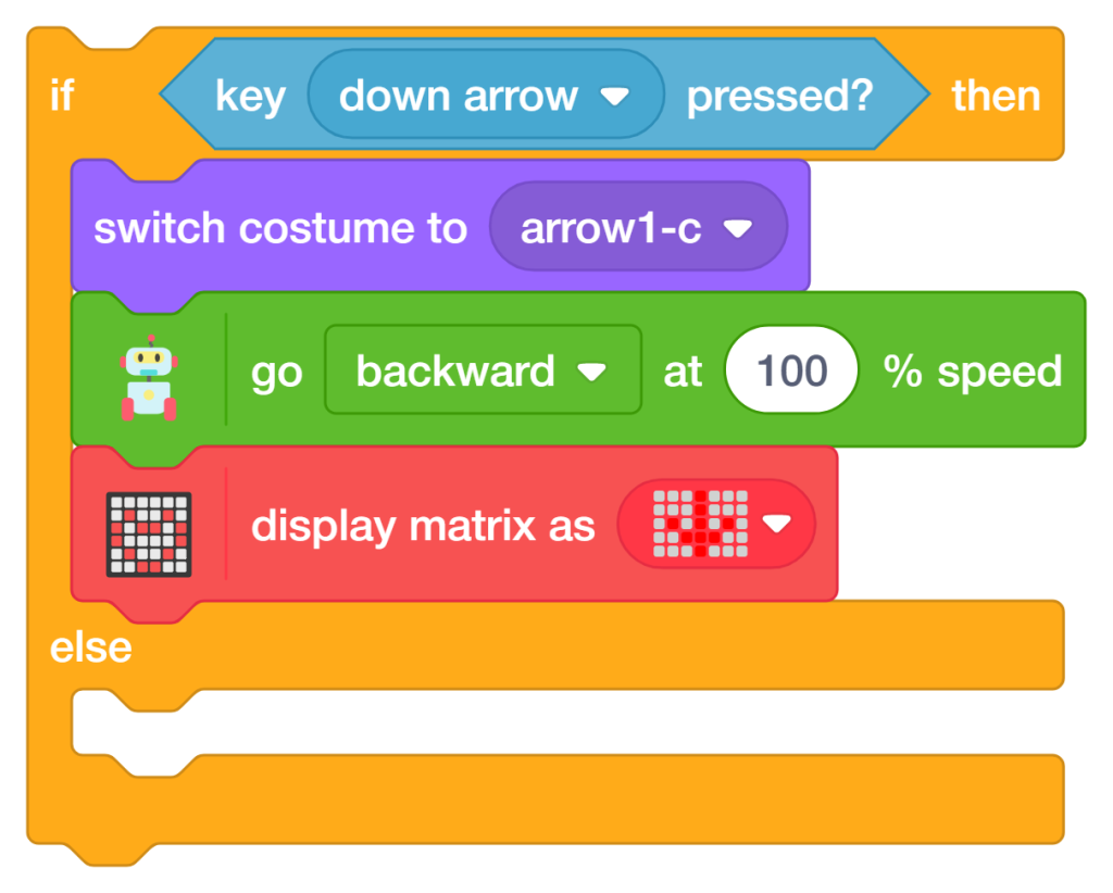
The second conditional checks whether the down arrow key is pressed. If true, Quarky moves backward at full speed and displays a backward direction symbol.
Add the ‘switch costume to (arrow1-c)’ block to indicate backward movement visually.
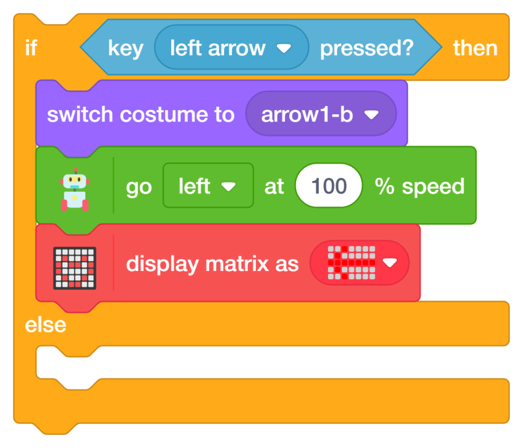
The third conditional checks whether the Left Arrow key is pressed. If true, Quarky moves left at full speed and displays a left direction symbol.
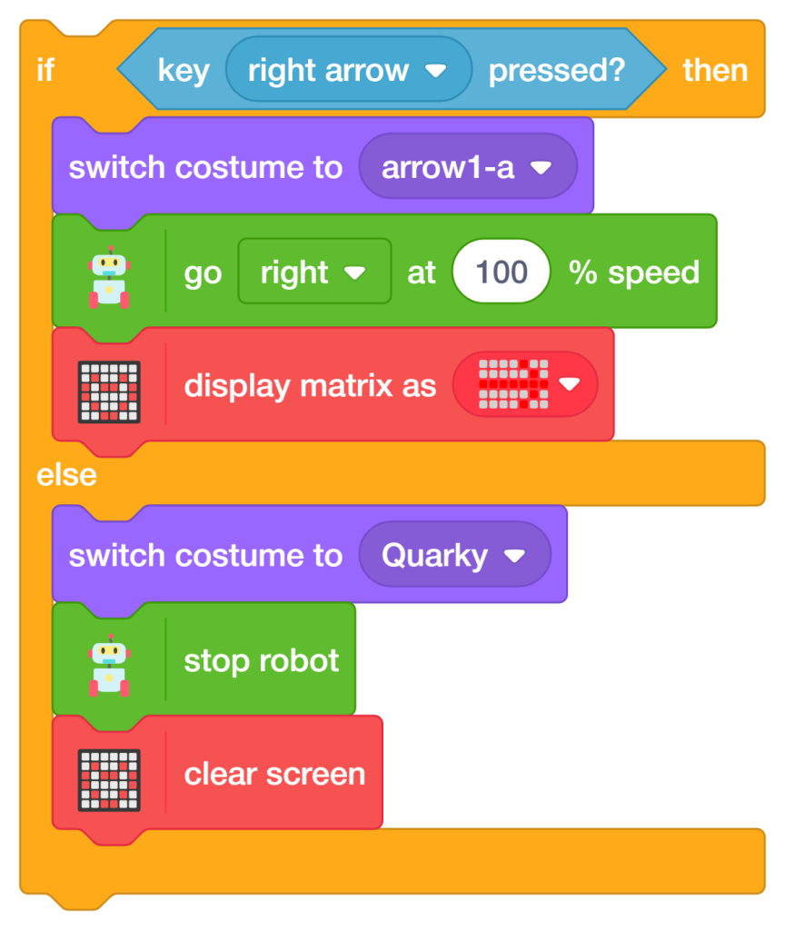
The fourth conditional checks whether the Right Arrow key is pressed. If true, Quarky moves right at full speed and displays a right direction symbol.
The final Else condition checks whether none of the arrow keys are pressed. If true, Quarky stops moving, clears the LED matrix display, and switches back to its default costume. This prevents unnecessary movement and keeps the robot safe.
A small delay is added inside the ‘Forever loop’ to make the robot movement smoother and more stable.
Congratulations! You have successfully programmed the Remote Control Quarky robot to respond to arrow key inputs using PictoBlox Block Coding. In this project, you:
These skills — keyboard input handling, conditional logic, robot navigation, RGB LED matrix display control, and real-time movement programming — are fundamental concepts used in robotics, automation systems, and AI-powered machines. You are not just controlling a robot; you are learning how intelligent machines interact with humans in real time!
In this activity, we will create a custom activity where you will be able to move the Mecanum robot in a square effortlessly along with making an Axe type figure.
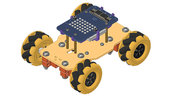
The Quarky Mecanum Wheel Robot is a type of robot that uses a special type of wheel to move. The wheel is made of four rollers mounted at 45- degree angles to the wheel’s hub. Each roller has its own motor and can spin in either direction. This allows the wheel to move in any direction, making it an ideal choice for navigating around obstacles.
Follow the steps:
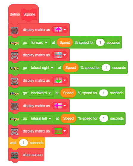
The main steps would include to display the lights in arrow forms before implementing the specific move. The moves would be implemented in the following order:
Forward -> Lateral Right -> Backward -> Lateral Left.
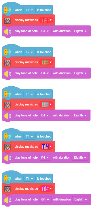
We will display the arrows with the help of Quarky LED’s and implement the code.
Example of arrow:
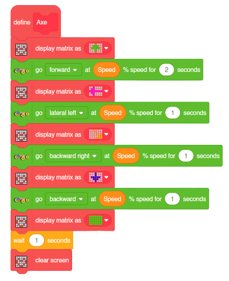
The main steps would include to display the lights in arrow forms before implementing the specific move. The moves would be implemented in the following order:
Forward ( 2 steps ) -> Lateral Left ( 1 step ) -> Backward Right ( 1 step ) -> Backward ( 1 step )
We will display the arrows with the help of Quarky LED’s and implement the code.
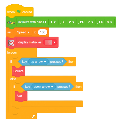
Now we will keep a specific condition on when to activate the Square Motion and when to activate the Axe Motion.
We will use the if-else conditions where on pressing the “up” arrow key, we will initiate the Square Motion and on pressing the “down” arrow key, we will initiate the Axe Motion with the help of Mecanum Robot.
Square Motion:
Axe Motion:
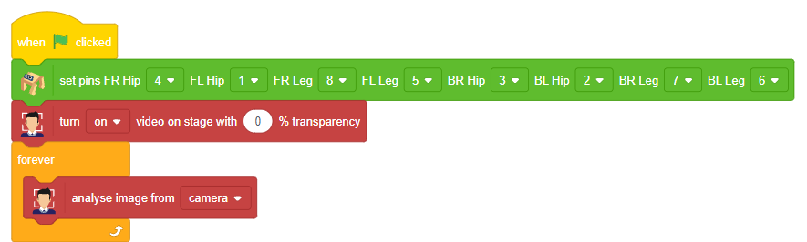
In this activity, students will program Quarky to detect a face’s position using the camera and respond with movements. Based on which direction the face is (left, right, or center), Quarky will display a pattern and move accordingly. This teaches camera-based input, angle calculations, and conditional movements.
![]()
90 + (x position of face ÷ 3) to decide how far the face is from the center.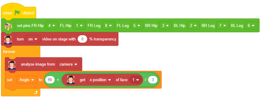
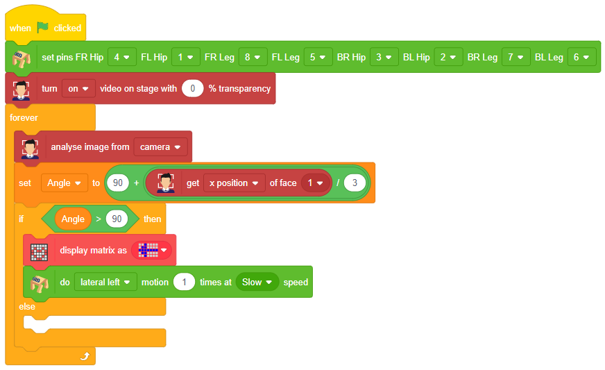
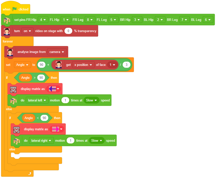
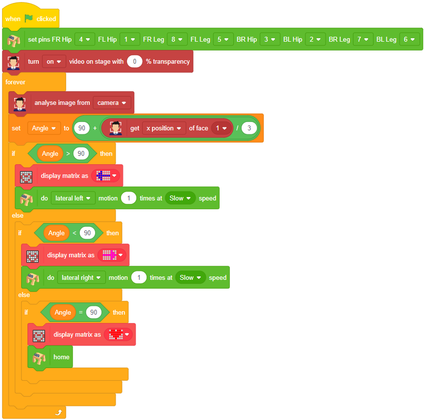

Our next step is to check whether it is working right or not. Whenever your face will come in front of the camera, it should detect it and as you move to the right or left, the head of your Quadruped robot should also move accordingly.
![]()
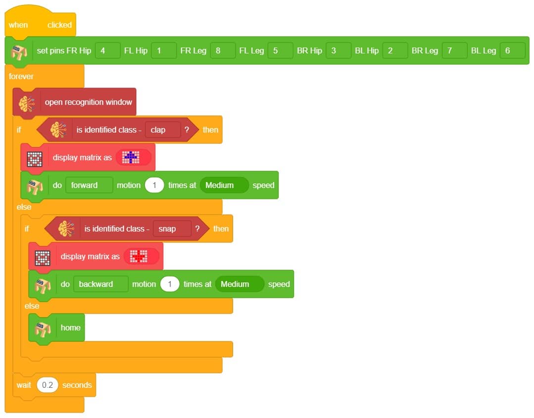
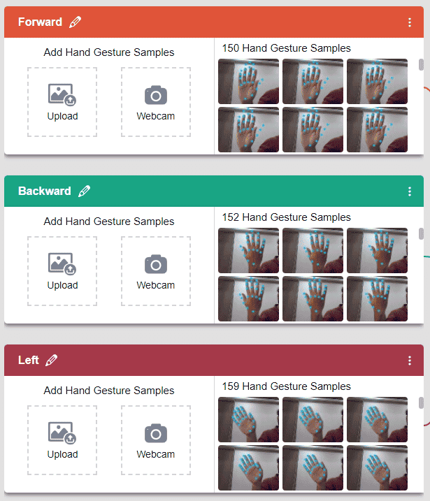
This project demonstrates how to use Machine Learning Environment to make a machine–learning model that identifies the hand gestures and makes the Quadruped move accordingly. learning model that identifies the hand gestures and makes the qudruped move accordingly.
We are going to use the Hand Classifier of the Machine Learning Environment. The model works by analyzing your hand position with the help of 21 data points.
Follow the steps below:
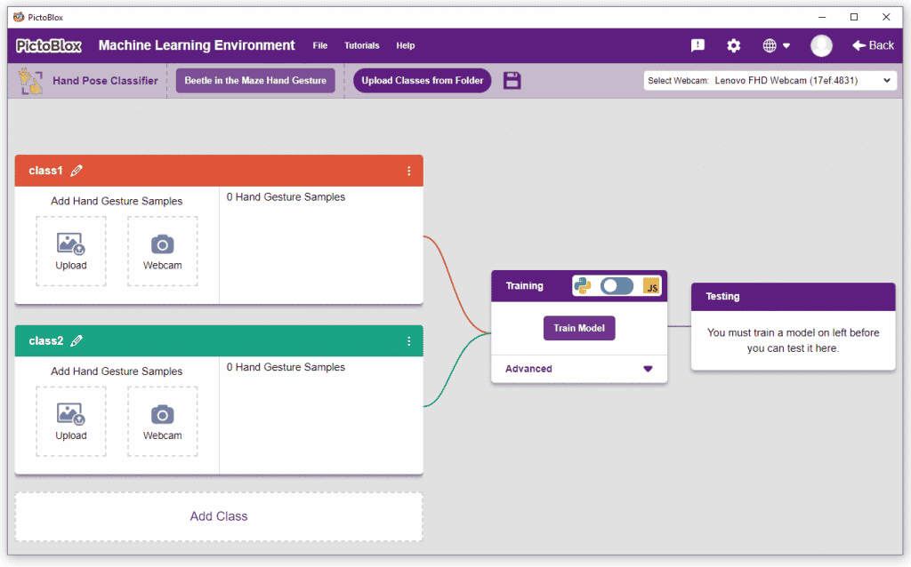
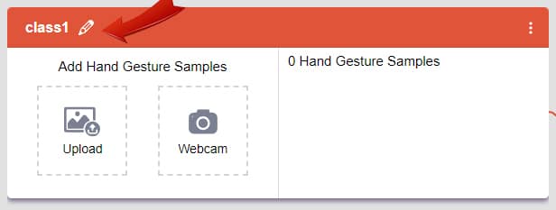
There are 2 things that you have to provide in a class:

You can perform the following operations to manipulate the data into a class.
We are going to use the Hand Classifier of the Machine Learning Environment.
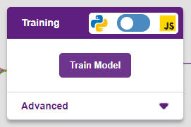
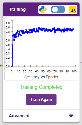
After data is added, it’s fit to be used in model training. In order to do this, we have to train the model. By training the model, we extract meaningful information from the hand pose, and that in turn updates the weights. Once these weights are saved, we can use our model to make predictions on data previously unseen.
The accuracy of the model should increase over time. The x-axis of the graph shows the epochs, and the y-axis represents the accuracy at the corresponding epoch. Remember, the higher the reading in the accuracy graph, the better the model. The range of the accuracy is 0 to 1.
The model will return the probability of the input belonging to the classes.You will have the following output coming from the model.
The Quadruped will move according to the following logic:
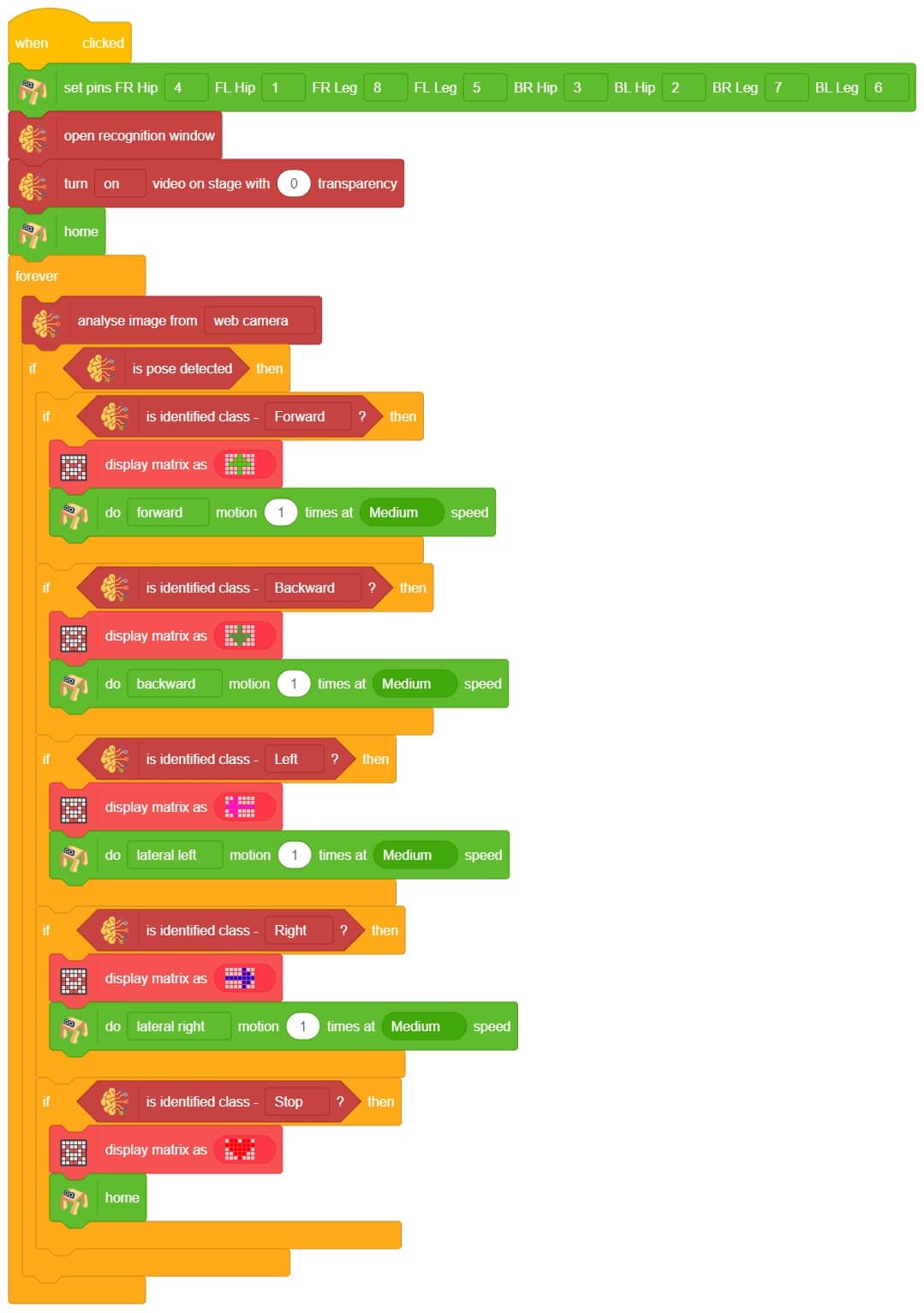

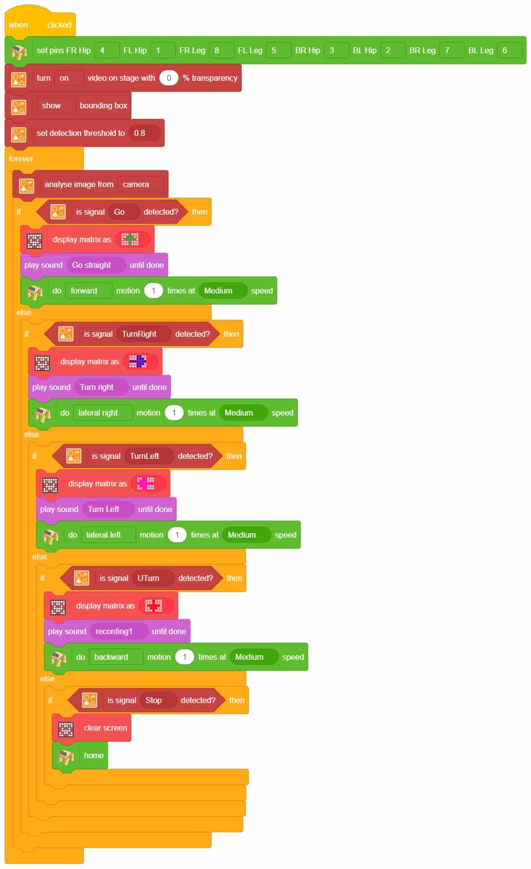
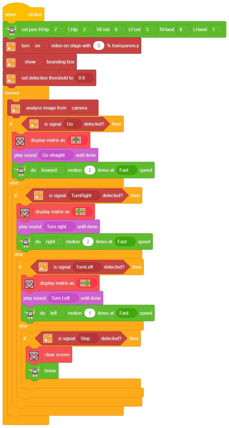
A sign detector Quadruped robot is a robot that can recognize and interpret certain signs or signals, such as hand gestures or verbal commands, given by a human. The robot uses sensors, cameras, and machine learning algorithms to detect and understand the sign, and then performs a corresponding action based on the signal detected.
These robots are often used in manufacturing, healthcare, and customer service industries to assist with tasks that require human-like interaction and decision-making.
A sign detector Humanoid robot is a robot that can recognize and interpret certain signs or signals, such as hand gestures or verbal commands, given by a human. The robot uses sensors, cameras, and machine learning algorithms to detect and understand the sign, and then performs a corresponding action based on the signal detected.
These robots are often used in manufacturing, healthcare, and customer service industries to assist with tasks that require human-like interaction and decision-making.
A Sound-Based Quadruped with Machine Learning refers to a Quadruped robot that can perceive and interact with its environment through sound-based sensing and uses machine-learning techniques to process and analyze the auditory data it receives.
Quadruped robots with machine learning have the potential to greatly enhance the way we interact with machines and each other, making communication more natural and intuitive while also enabling new applications in fields such as healthcare, education, and entertainment.
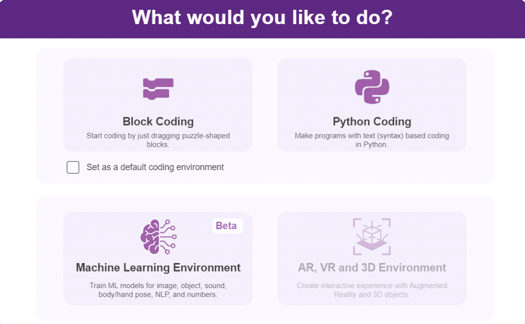
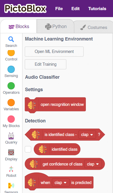
In this activity, we will use the Machine Learning Environment of the Pictoblox Software. We will use the Audio Classifier of the Machine Learning Environment and create our custom sounds to control the Quadruped.
Follow the steps below to create your own Audio Classifier Model:
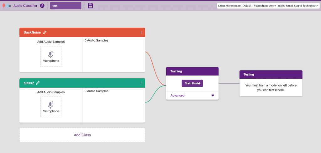
Note: You can add more classes to the projects using the Add Class button.
You can perform the following operations to manipulate the data into a class.
Note: You will only be able to change the class name in the starting before adding any audio samples. You will not be able to change the class name after adding the audio samples in the respective class.
After data is added, it’s fit to be used in model training. To do this, we have to train the model. By training the model, we extract meaningful information from the hand pose, and that in turn updates the weights. Once these weights are saved, we can use our model to make predictions on data previously unseen.
The accuracy of the model should increase over time. The x-axis of the graph shows the epochs, and the y-axis represents the accuracy at the corresponding epoch. Remember, the higher the reading in the accuracy graph, the better the model. The range of accuracy is 0 to 1.
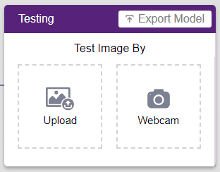
To test the model simply, use the microphone directly and check the classes as shown in the below image:
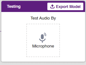
You will be able to test the difference in audio samples recorded from the microphone as shown below:
Click on the “Export Model” button on the top right of the Testing box, and PictoBlox will load your model into the Block Coding Environment if you have opened the ML Environment in the Block Coding.
The Quadruped will move according to the following logic:
Note: You can add even more classes with different types of differentiating sounds to customize your control. This is just a small example from which you can build your own Sound Based Controlled Quadruped in a very easy stepwise procedure.