Table of Contents

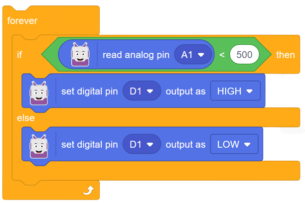
set digital pin () output as ()

Description

This block enables users to set the digital state of a digital pin to either a High (5V) or Low (0V) voltage output.

Available pins

  1. evive: 25 digital pins available as digital output: 2 to 18 and 20 to 27

The pin can be selected from the drop-down menu.

evive Notes Icon
Note: This block is available in both Upload mode and Stage mode.

Example

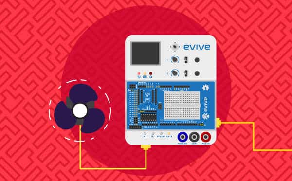
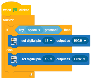
  1. Controlling Pin 13 LED using the Space key. If the output is High, the LED glows, and if the output is Low, the LED turns off.
    digital write example
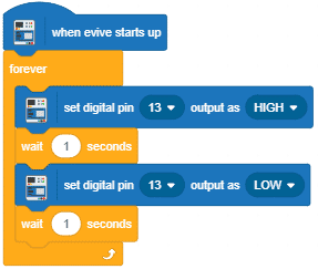
  2. LED blinking.
    digital write example 2

Example

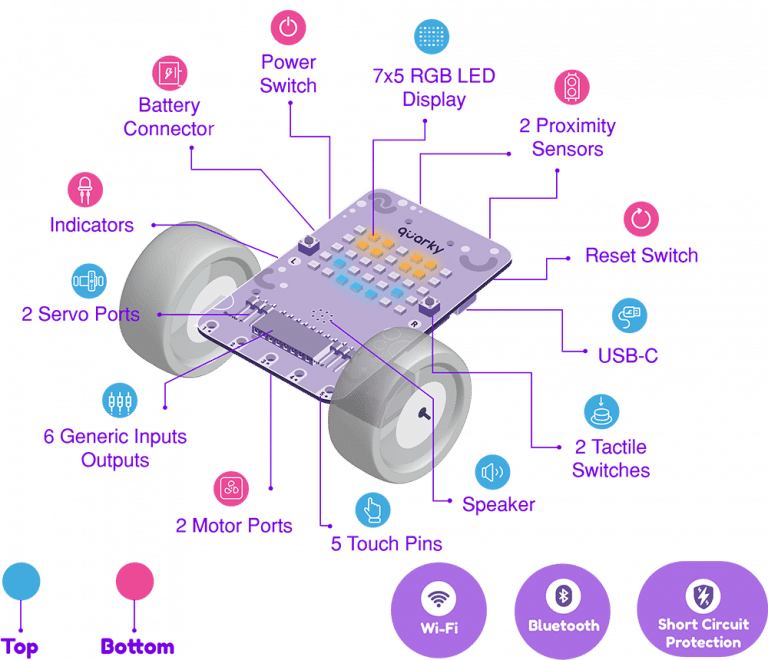
Discover Quarky, a versatile microcontroller for programming various projects, from basic to advanced levels in robotics and AI.
Introduction

Quarky is a powerful microcontroller that allows for custom programming of projects, ranging from basic to advanced levels. With various built-in features such as sensors, actuators, and a speaker, Quarky becomes the perfect companion for those venturing into the world of robotics and AI. Its compact size and plug-and-play functionality make it an ideal choice for students eager to learn and experiment with robotics.


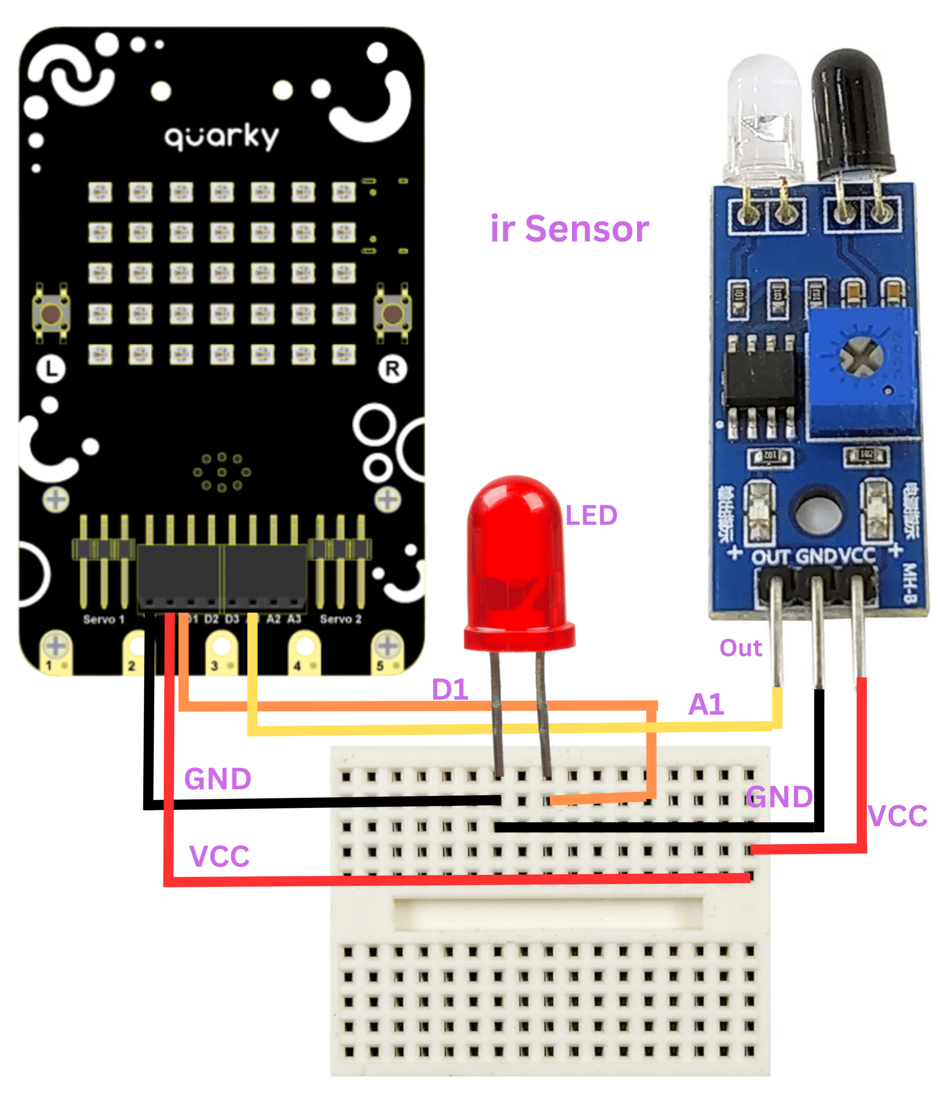
Circuit Diagram:


Code:

Follow these steps to implement the code using Pictoblox for Quarky to control the LED based on the IR sensor’s readings:

  1. Open Pictoblox and create a new file in block coding.
  2. Go to boards and select Quarky.
  3. Add an if-then-else block from the event palette.
  4. From the operators, add the “less than” operator in the conditional space.
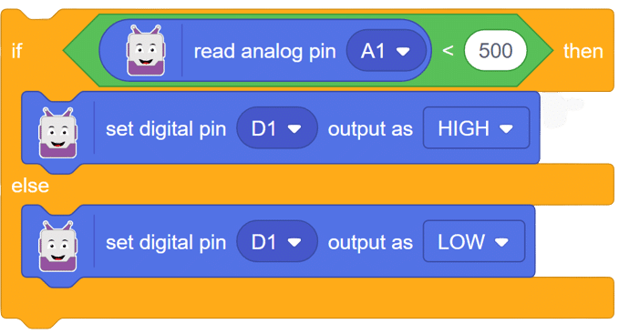
  5. Go to Quarky and add the “read analog pin ()” block into the first space of the “less than” operator. Change the value to 500.
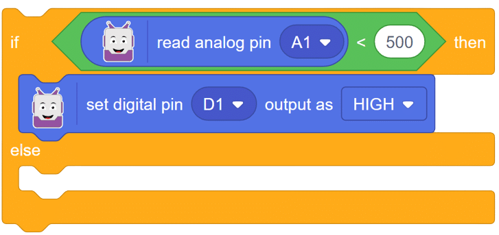
  6. Use the “set digital pin () as ()” block from Quarky to turn ON the LED connected at D1 if the value is less than 500.
  7. If the value is above the set value (500), then the LED must turn OFF.
  8. Place the above set of code in the “forever” loop.
  9. Now add “when flag clicked” at the start in the script.

Script:

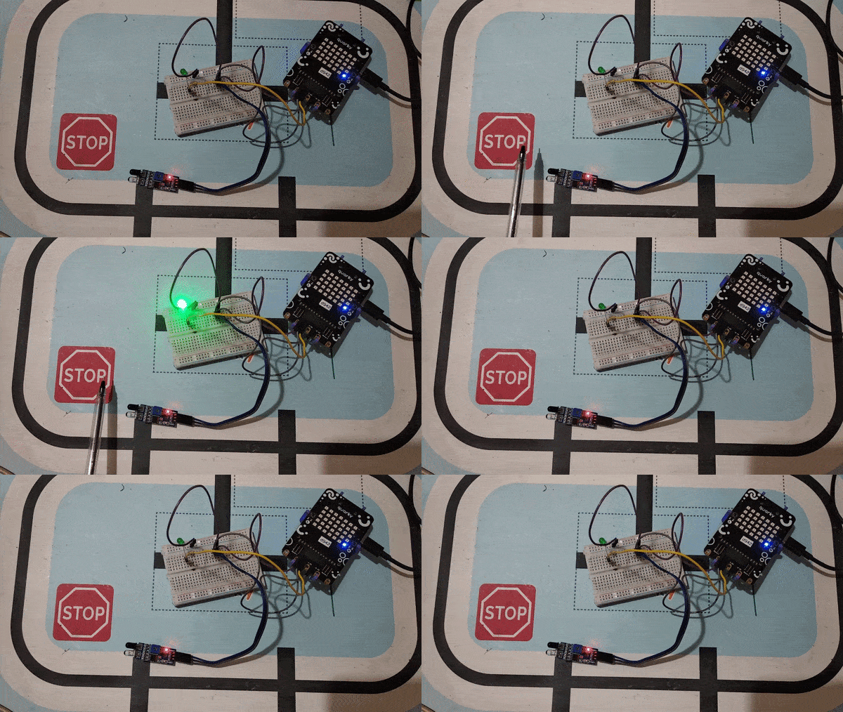
Output:

In this comprehensive introduction, you have learned about Quarky, the versatile microcontroller, and its potential in robotics and AI projects. Explore its various features, sensors, and plug-and-play functionality. Follow our step-by-step guide to set up the circuit with the IR sensor and LED, and program Quarky using Pictoblox’s block coding. Witness the successful implementation through the final script and output, experiencing the magic of Quarky in action!


Read More
Learn about LDR (Light Dependent Resistor) sensor and its analog properties while creating a fun activity using Quarky.
Introduction

The LDR (Light Dependent Resistor) sensor is a renowned analog-type sensor that adapts its resistance according to surrounding light intensity. With its ability to fluctuate resistance based on light changes, the LDR plays a vital role in various light-sensing applications. Though typically designed as a two-pin sensor, it is also available as a three-pin module, offering enhanced features and versatility.

In this example, we embark on a fun activity using the LDR sensor and Quarky. Through this engaging experience, you will grasp essential concepts like analog and PWM signals, creating an exciting learning journey. So, let’s dive in and explore the wonders of LDR and Quarky together!

Circuit Diagram:
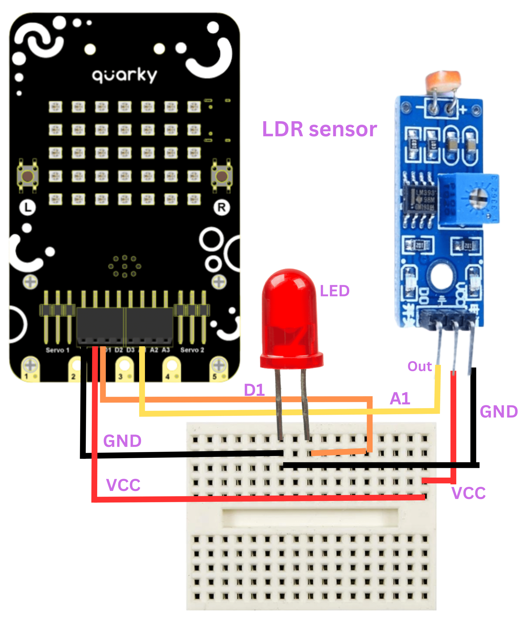
Code:

Follow these steps to implement the code using Pictoblox for Quarky and explore the behavior of the LDR sensor:

  1. Open Pictoblox and create a new file.
  2. From the board menu, select Quarky and connect it to Pictoblox.
  3. Add the “when flag clicked” event block into the scripting area.
  4. Create two variables named “brightness” and “LDR value” from the “my variables” category and set them both to 0.
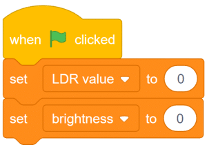
  5. Add a forever loop to ensure continuous execution of the code.
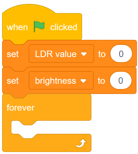
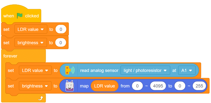
  6. From the sensor palette of Quarky, drag the block read analog sensor () at pin () and the LDR value equal to the value of this block as shown below.
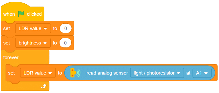
  7. Map this value to change the range from 0-4095 to 0-255 (0V-5V) and store the result in the “brightness” variable.
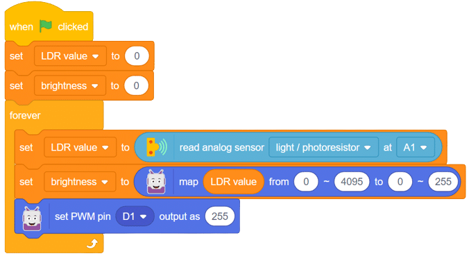
  8. Go to the Quarky palette and drag the “set PWM pin() output as()” block. Select D1 from the drop-down menu.
  9. Set the PWM value as the “brightness” variable.
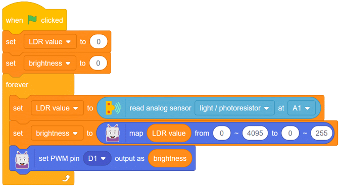
 

With these steps, your script is complete, and Quarky is ready to interact with the LDR sensor.

Output:

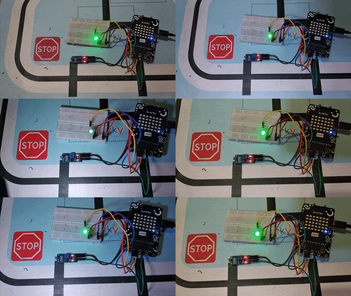
Through this exciting project, you have learned about the LDR sensor, its analog characteristics, and how Quarky can control an LED based on the light intensity sensed by the LDR. Delve deeper into the concepts of analog and PWM signals, making your robotics journey even more captivating with Quarky! Stay curious and keep exploring the endless possibilities!
Read More
Learn how to interface a relay with Quarky, the versatile microcontroller, to control high-voltage appliances using electromagnetic induction.
Introduction

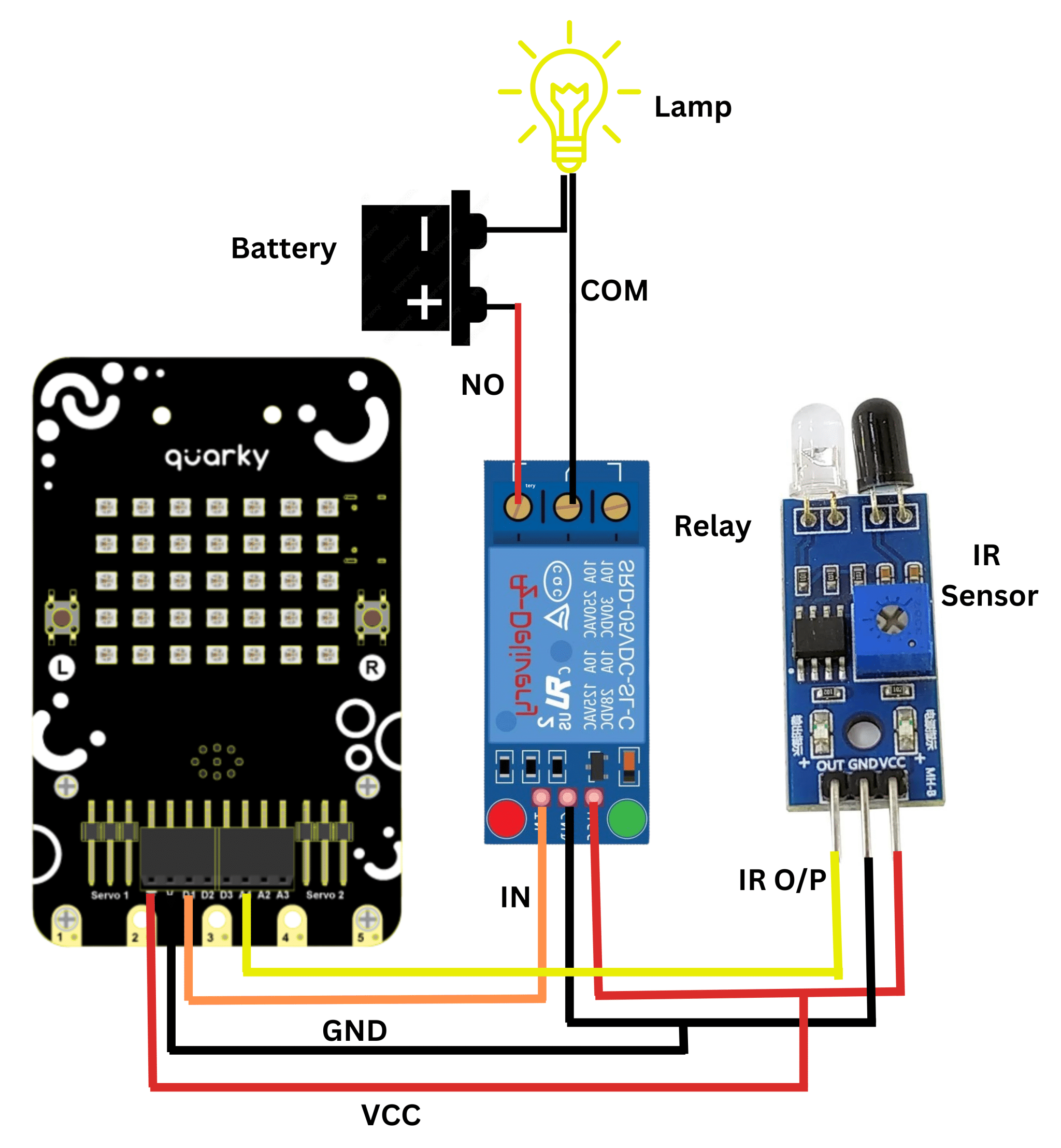
A relay is an electromagnetic switch that works on the principle of electromagnetic induction. A Realy is used to control the high voltage appliances using the microcontrollers. The relay has a primary side which is need to be connected to the controller and the secondary side is need to be connected to the load, for example, motor, light bulb, fan, etc. The primary side has 3 pins named as VCC, GND, and IN.  secondary also has connections named as Common(COM), Normally Open(NO), and Normally Closed (NC).

5V Single-Channel Relay Module - Pin Diagram, Specifications, Applications, Working

In this example, we will be interfacing a relay with Quarky,  We already know how to connect IR-Sensor with Quarky, and now we will be using ir sensor to trigger the relay. Let’s begin.

Circuit Diagram:

Code:

  1. Connect it Sesnor and Realy with Quarky as per the above circuit diagram.
  2. Open pictoblox and create a new file.
  3. Go to boards menu and select Quarky.
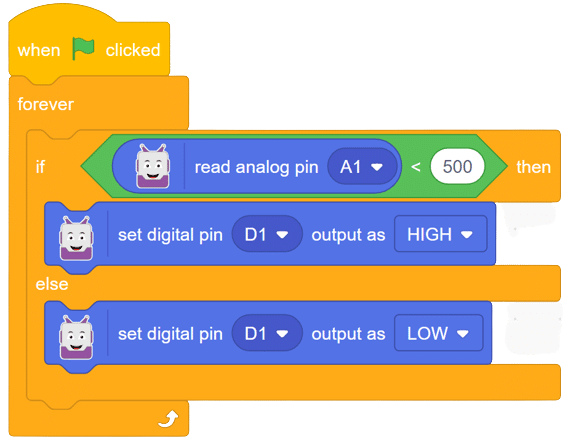
  4. Add an if-then-else block from the event palette.
  5. From the operators, add the “less than” operator in the conditional space.
  6. Go to Quarky and add the “read analog pin ()” block into the first space of the “less than” operator. Change the value to 500.
  7. Use the “set digital pin () as ()” block from Quarky to trigger relay connected at D1 if the value is less than 500.
  8. If the value is above the set value (500), then the LED must turn OFF.
  9. Place the above set of code in the “forever” loop.
  10. Now add “when flag clicked” at the start in the script.

Script:

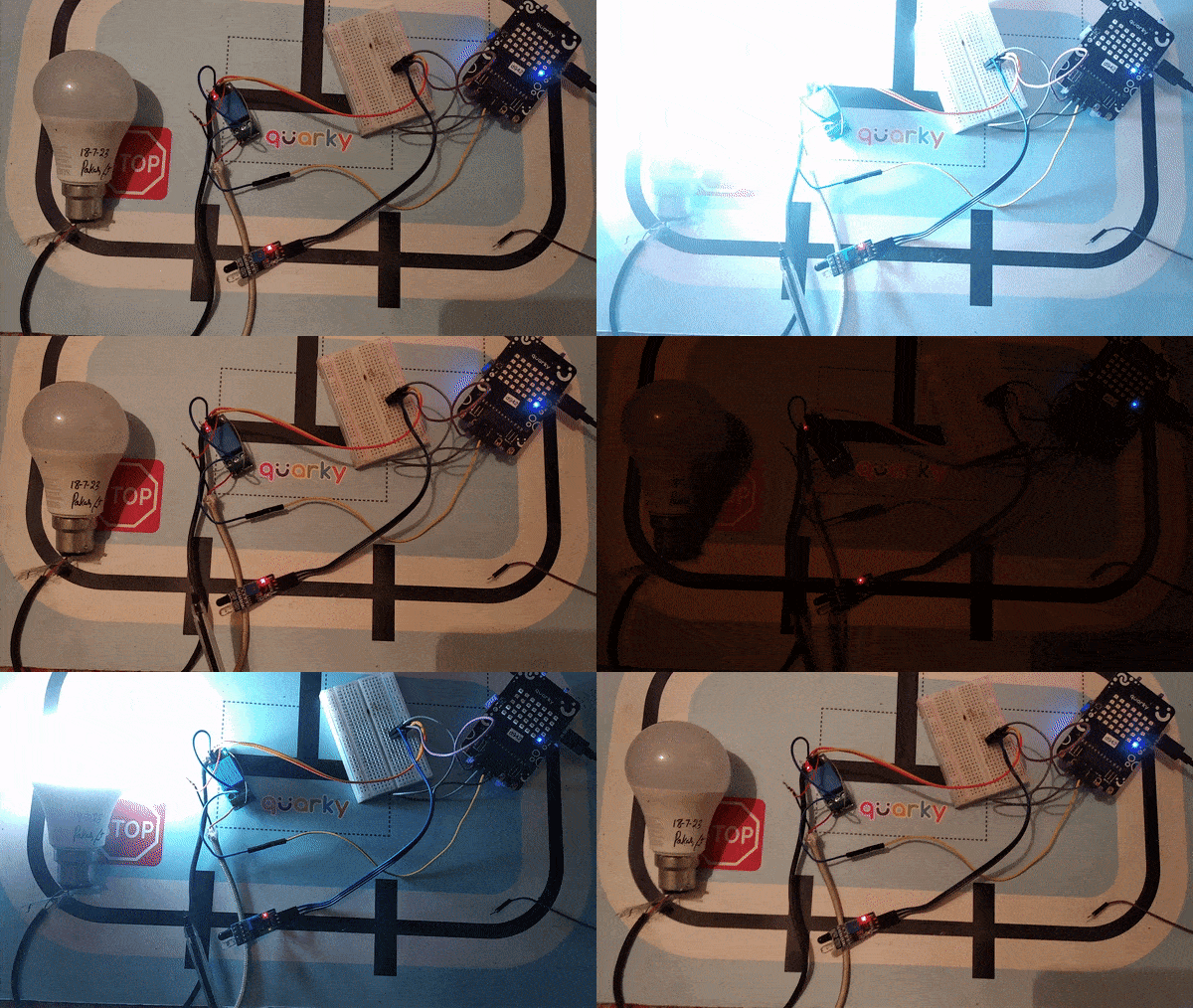
Output:

In this comprehensive introduction, you have learned about Relay and its interfacing with Quarky,  the versatile microcontroller, and its potential in robotics and AI projects. Explore its various features, sensors, and plug-and-play functionality.

Read More
All articles loaded
No more articles to load