Introduction
A relay is an electromagnetic switch that works on the principle of electromagnetic induction. A Realy is used to control the high voltage appliances using the microcontrollers. The relay has a primary side which is need to be connected to the controller and the secondary side is need to be connected to the load, for example, motor, light bulb, fan, etc. The primary side has 3 pins named as VCC, GND, and IN. secondary also has connections named as Common(COM), Normally Open(NO), and Normally Closed (NC).

In this example, we will be interfacing a relay with Quarky, We already know how to connect IR-Sensor with Quarky, and now we will be using ir sensor to trigger the relay. Let’s begin.
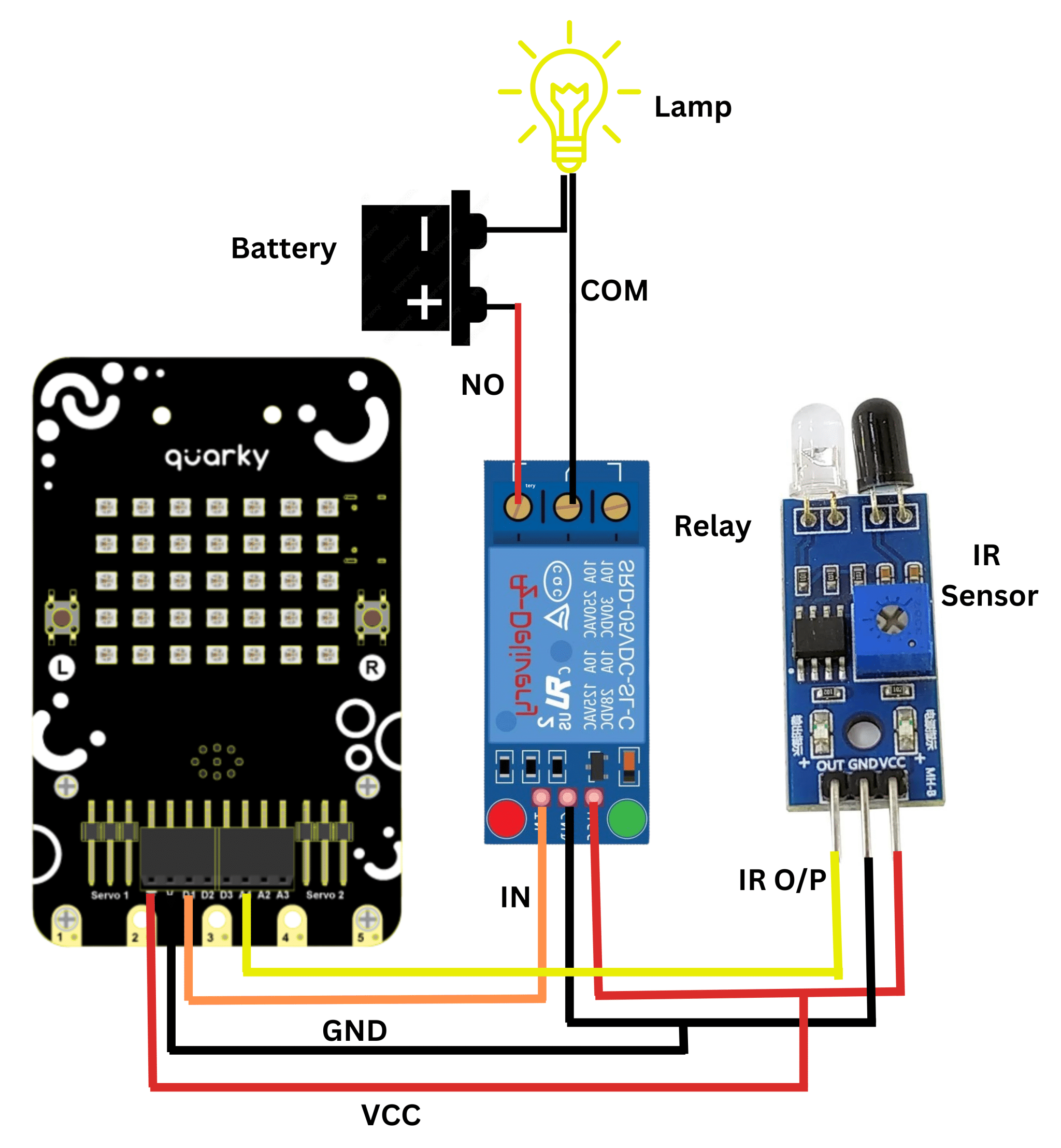
Circuit Diagram:
Code:
- Connect it Sesnor and Realy with Quarky as per the above circuit diagram.
- Open pictoblox and create a new file.
- Go to boards menu and select Quarky.
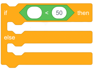
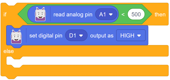
- Add an if-then-else block from the event palette.

- From the operators, add the “less than” operator in the conditional space.
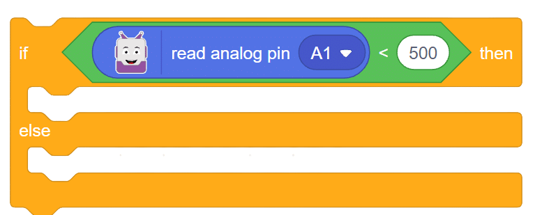
- Go to Quarky and add the “read analog pin ()” block into the first space of the “less than” operator. Change the value to 500.
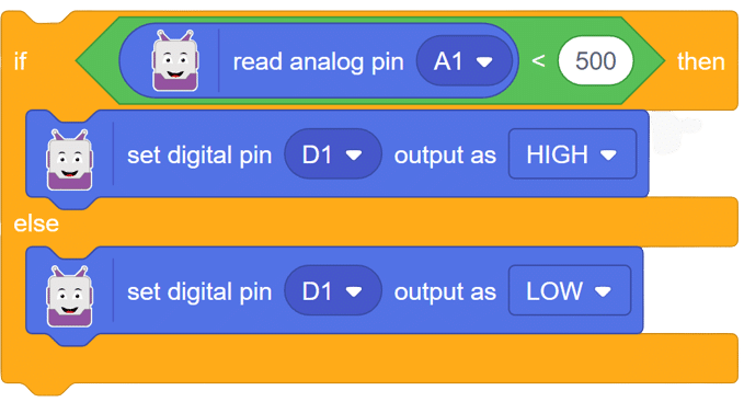
- Use the “set digital pin () as ()” block from Quarky to trigger relay connected at D1 if the value is less than 500.
- If the value is above the set value (500), then the LED must turn OFF.
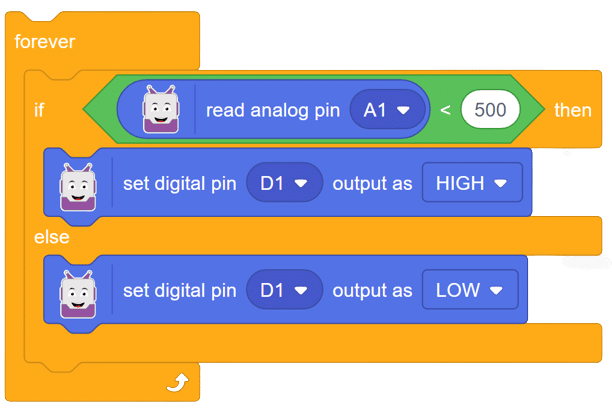
- Place the above set of code in the “forever” loop.
- Now add “when flag clicked” at the start in the script.
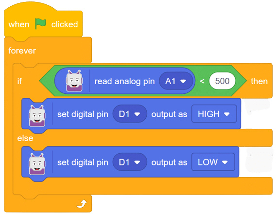
Script:
Output:
In this comprehensive introduction, you have learned about Relay and its interfacing with Quarky, the versatile microcontroller, and its potential in robotics and AI projects. Explore its various features, sensors, and plug-and-play functionality.