


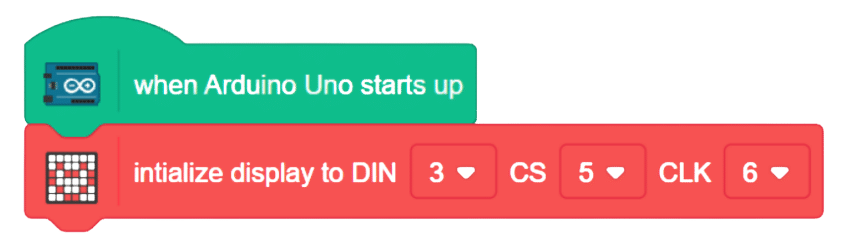
The block sets up an 8x8 Dot Matrix display and assigns the pins of the display (DIN, CS, CLK) to be connected to the Arduino board. The code assigns the name of the display to the pins for easy referencing and establishes communication between the Arduino board and the display.

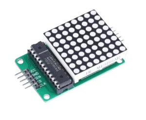
8*8 Dot Matrix with Arduino
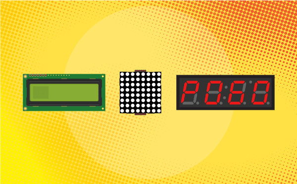
In this project, we will explore how to effectively use the 8×8 LED dot matrix with an Arduino Uno board. The 8×8 LED matrix contains 64 LEDs arranged in an 8×8 grid, forming a versatile display module. By connecting each row and column to digital pins, we can control the LED matrix and showcase a wide array of patterns, emojis, and animations. Additionally, cascading multiple dot matrices together enables us to expand the display without the need for extra pins.
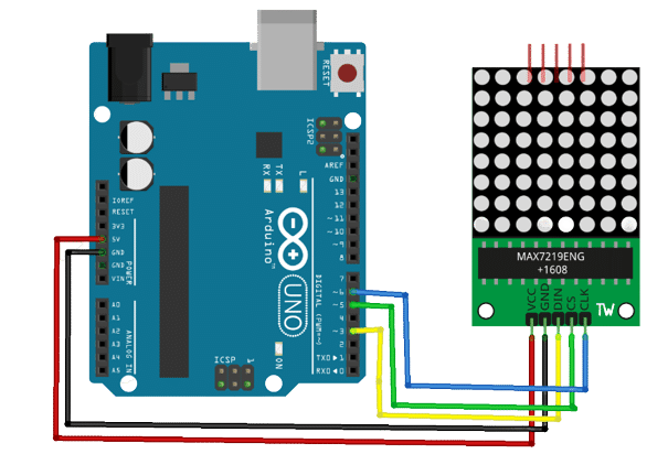
Circuit Diagram
Code
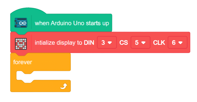
- Add when Arduino starts up.
- Initialize the display module and pin connections with the Arduino.
- From control palette add forever block.
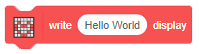
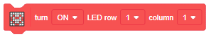
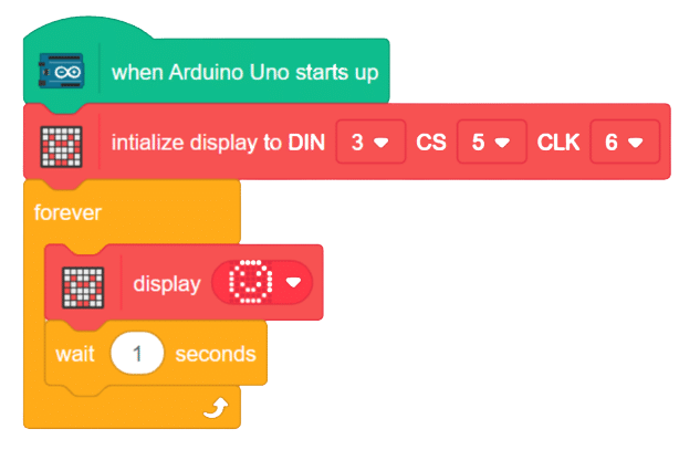
- To display any emoji or pattern use the display block.
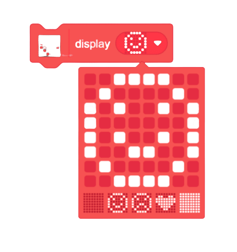
- Chose any of the emoji or emotion and add in the forever loop and add a time delay.
- Again chose one different emoji or emotion and add a time delay.
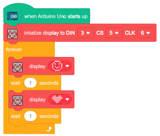
- With this your script is complete and upload the C++ code in the Arduino using the upload button.
Script