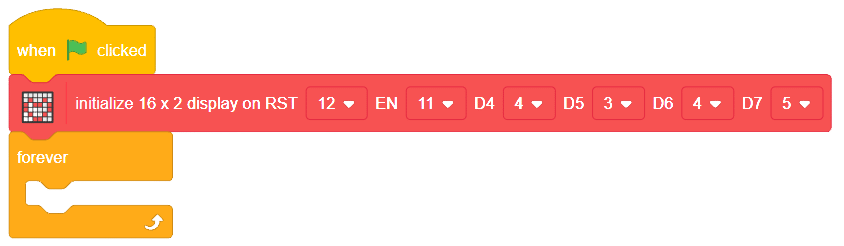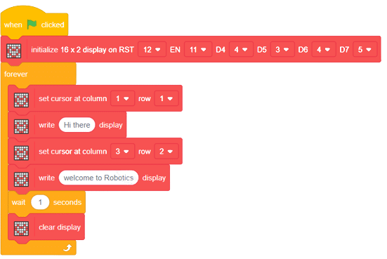


The block does the pin assignments for a 16x2 display module. The specific pins that are assigned are for the Reset (RST), Enable (EN), Data 4 (D4), Data 5 (D5), Data 6 (D6), and Data 7 (D7) pins of the module. This initialization enables the code to use the 16x2 display.
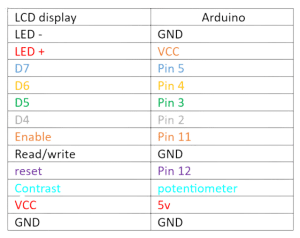
LCD Module Pinout
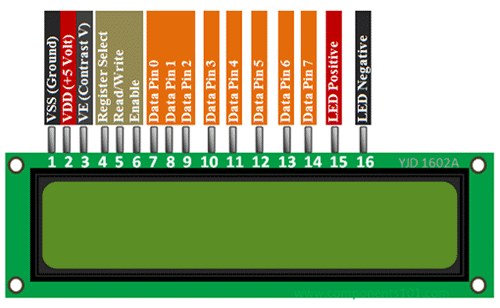
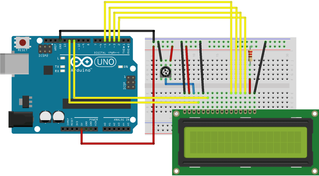
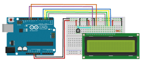
Circuit Diagram
To wire your LCD screen to your board, connect the following pins:
- LCD RS pin to digital pin 12
- LCD Enable pin to digital pin 11
- LCD D4 pin to digital pin 5
- LCD D5 pin to digital pin 4
- LCD D6 pin to digital pin 3
- LCD D7 pin to digital pin 2
- LCD R/W pin to GND
- LCD VSS pin to GND
- LCD VCC pin to 5V
- LCD LED+ to 5V through a 220-ohm resistor
- LCD LED- to GND
Additionally, wire a 10k potentiometer to +5V and GND, with its wiper (output) to LCD screens VO pin (pin3).