

Arduino Mega

Arduino_MEGA
Extension Description
Learn how to connect and program Arduino Mega using PictoBlox Block Coding. This beginner-friendly guide explains board selection, USB serial connection, Stage Mode, Upload Mode, and the Arduino Mega blocks available in PictoBlox.

Introduction

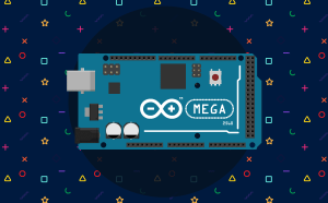
Arduino Mega is a microcontroller board designed for electronics, robotics, automation, and projects that require many input and output connections. Its larger number of pins makes it suitable for controlling multiple sensors, motors, displays, LEDs, and other electronic components.

PictoBlox makes programming the Arduino Mega easier through its block-coding environment. Instead of writing code manually, you can drag and connect blocks to control digital pins, analog pins, PWM outputs, tones, and timers.

In this documentation, you will learn about the Arduino Mega extension, connect Arduino Mega to PictoBlox, and understand the purpose of each Arduino Mega block.

Connecting Arduino Mega to PictoBlox

Follow these steps to connect your Arduino Mega board to PictoBlox.

Step 1: Connect Arduino Mega

Connect the Arduino Mega board to your computer using a compatible USB cable. Make sure the board’s power LED turns ON after connecting it.
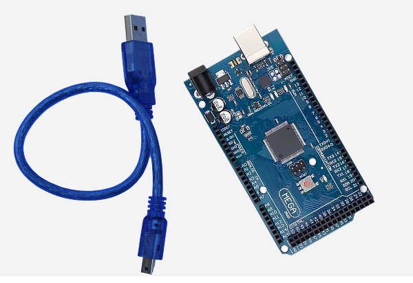
Connect Arduino mega to laptop

Step 2: Open PictoBlox

Open PictoBlox on your computer. Select the Block Coding environment.
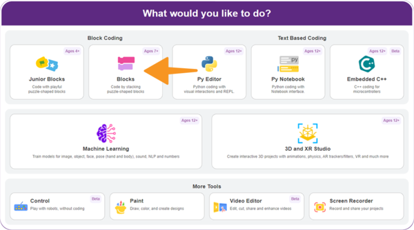
Select the Block Coding environment
Step 3: Select Arduino Mega Board

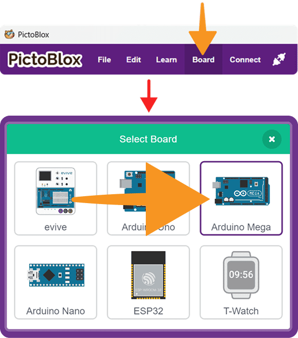
  1. Click on the Board menu from the top toolbar.
  2. Select Arduino Mega from the available board options.
    Select Arduino Mega Board

Step 4: Select the Serial Port

Click on the Connect menu. Under Serial Ports (USB), find the port connected to the Arduino device.
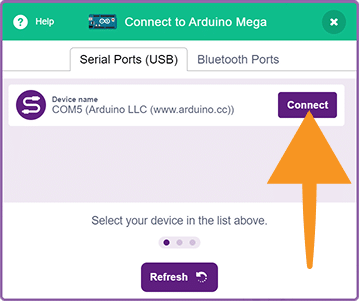
Select the Serial Port
Click Connect beside the correct device.

Step 5: Confirm the Connection

Wait while PictoBlox establishes communication with the Arduino Mega. After a successful connection, the screen will display the connected serial port, such as:
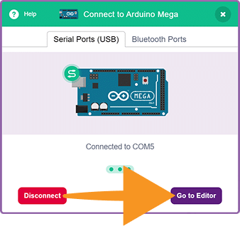
Confirm the Connection

Click Go to Editor to open the coding workspace and start programming your Arduino Mega.

Step 6: Check Arduino Mega Blocks

After connecting the board, select the Arduino Mega category from the block palette.
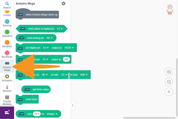
Arduino Mega Blocks with extension

You should see the following blocks:

  • when Arduino Mega starts up
  • read status of digital pin
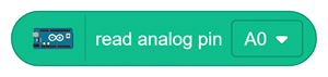
  • read analog pin
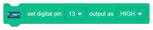
  • set digital pin output
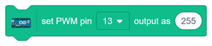
  • set PWM pin output
  • play tone
  • get timer value
  • reset timer
  • cast
  • map

These blocks allow you to control the built-in functionalities of Arduino Mega using PictoBlox.

PictoBlox Modes for Arduino Mega

1. Stage Mode

  • Use Stage Mode when you want Arduino Mega to communicate with PictoBlox in real time.
  • The board must remain connected to the computer while the project is running.

2. Upload Mode

  • Use Upload Mode when you want to upload the complete program to Arduino Mega.
  • After uploading, the board can run the program independently without remaining connected to PictoBlox.
Read More

PictoBlox Blocks

The read status of digital pin () block checks whether the selected Arduino Mega digital pin is HIGH or LOW. It returns True when the pin is HIGH and False when the pin is LOW.
The read analog pin () block reads the value received by a selected analog pin on Arduino Mega. It returns a value from 0 to 1023, representing an input voltage of approximately 0V to 5V.
The set digital pin () output as () block sets a selected Arduino Mega digital pin to HIGH or LOW. Use it to control LEDs, buzzers, relays, and other digital output devices.
The set PWM pin () output as () block controls the PWM output of a selected Arduino Mega pin from 0 to 255. It can be used to adjust LED brightness, motor speed, and other PWM-compatible devices.
The play tone on () of note () & beat () block plays a selected musical note on an Arduino Mega digital pin. It is useful for creating buzzer sounds, alarms, melodies, notifications, and audio feedback.
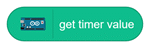
The get timer value block returns the time elapsed since Arduino Mega started or the timer was reset. The returned time is measured in milliseconds.
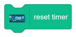
The reset timer block sets the current timer value back to 0. Use it when you want to begin measuring a new time interval.
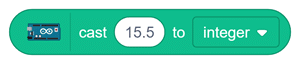
The cast () to () block converts a given value into an integer or float. It helps provide the correct data type for calculations and other blocks.
The map () from ()–() to ()–() block converts a value from one numerical range to another. For example, it can map an analog reading from 0–1023 to a PWM output from 0–255.
All articles loaded
No more articles to load
Table of Contents