



Introduction
Push buttons are incredibly popular electronic components found in everything from your TV remote to gaming controllers! Learn what a push button is, how state-toggling logic works, how to interface an LED and a push button with the ESP32 board, and program them with ease in PictoBlox – our Scratch blocks-based graphical programming platform with advanced hardware interaction abilities. Once you’re equipped with the basic knowledge of tracking variable states, reading digital inputs, and handling signal debouncing, we’ll show you how to build a smart light switch and other exciting DIY automation projects using your ESP32.
To work in PictoBlox, you’ll first need to download it from HERE.
Ready? Set. Go!
Prerequisites
- ESP32 Board
- Laptop or Computer
- PictoBlox installed on the system
- Push Switch
How to connect with ESP32
- First, open PictoBlox.
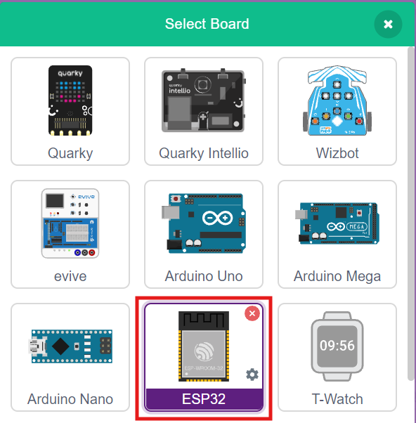
- Click on the Board tab on the toolbar and select ESP32.
- Next, click on the Connect button and select the appropriate serial port.
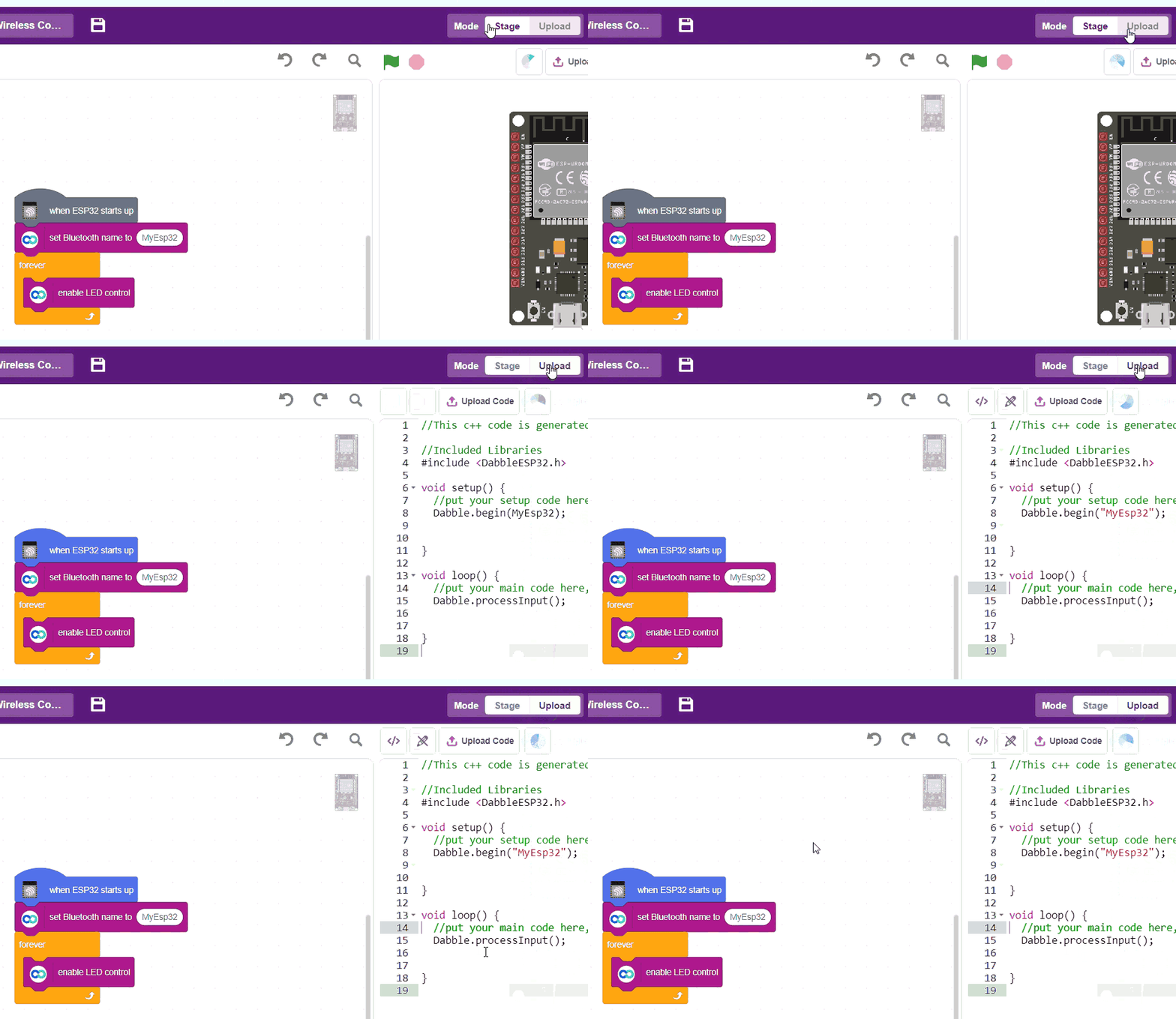
- In the top right corner, there is a toggle button named Mode. This button is used to switch between the two working modes of PictoBlox, namely the stage mode and the upload mode.
- Switch to Upload mode by toggling this button. You’ll observe some changes in the UI.
Connection Diagram
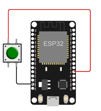
LED and Push Button Connection
- Connect the Ground Pin of the Push Button to GND in ESP32.
- Connect the Digital Input of the Push Button to PWM D4 Digital Pin in ESP32.
Step-by-Step Block Coding Guide
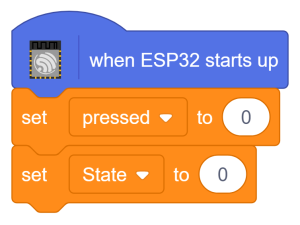
- Go to the ESP32 palette and drag the ‘when ESP32 starts up’ block into the scripting area.
- Go to the Variables palette and create a new variable by clicking on Make a Variable.Set its name as ‘pressed‘.
- Create another Variable named ‘State‘ by clicking on Make a Variable from Variables palette.
- Underneath ‘when ESP32 starts up’ add a ‘set () to ()‘ block. Use the pressed variable and set its value to ‘0‘.
- Add another ‘set () to ()‘ block. Use the State variable and set its value to ‘0‘.
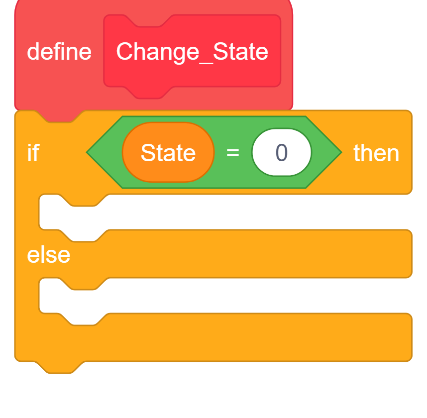
- Create a new block named ‘Change_State’ by clicking on Make a Block in My Blocks palette. A ‘define (Change_State)’ block will appear in your Scripting Area.
- Underneath the ‘Change_State‘ block, add the ‘if () then else’ block from the Control palette.
- Inside the if condition, add the ‘equals to‘ block from the Operators palette.
- Add the State variable in the left side of ‘equals to‘ block. For the right side, set the value to ‘0‘.
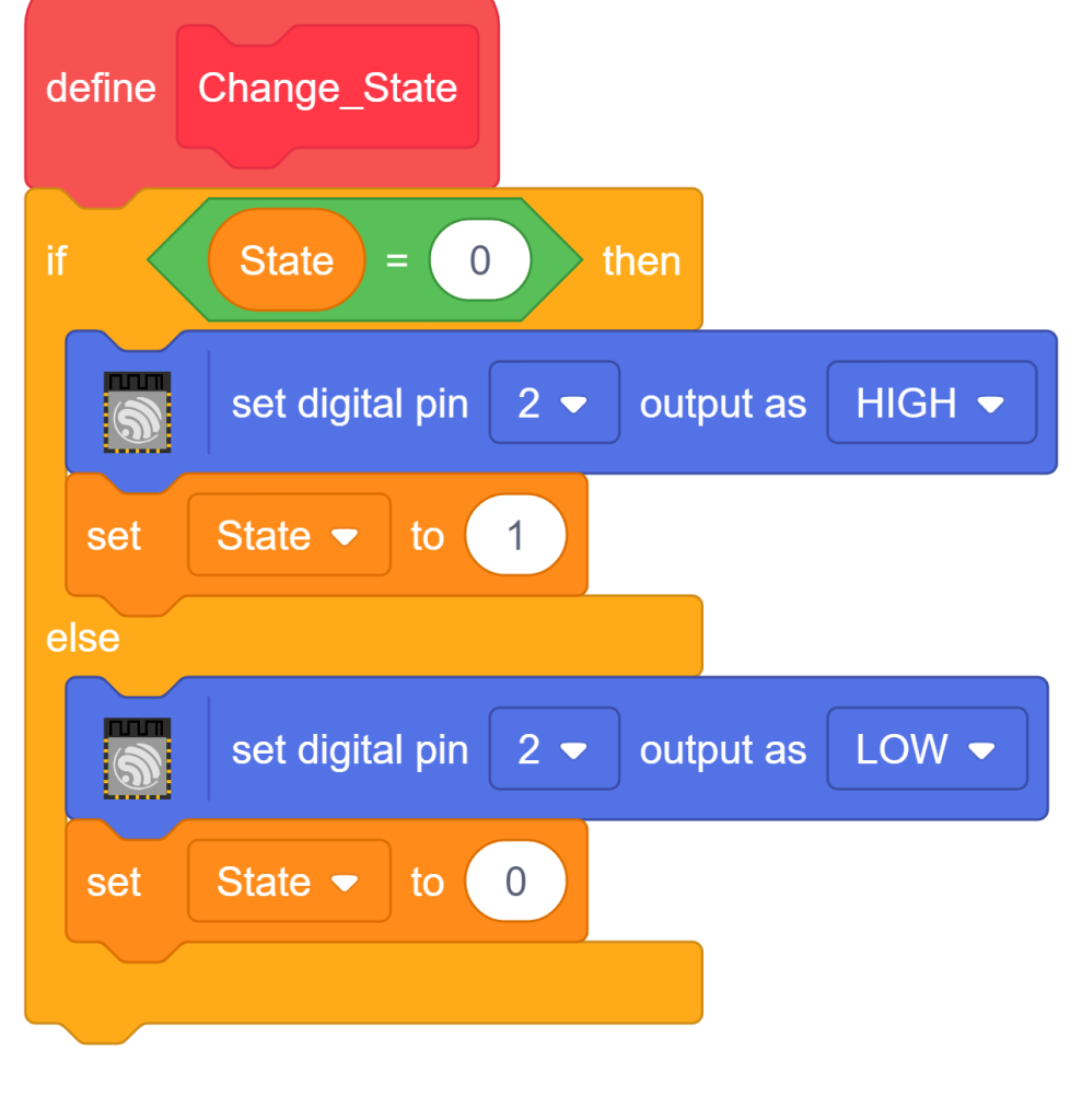
- Add the ‘set digital pin () output as ()‘ block from the ESP32 palette. Use the Digital pin ‘2‘ and set its output as ‘HIGH‘.
- Add the ‘set () to ()’ block from the Variables palette. Use the ‘State‘ variable and set its value to ‘1‘.
- Inside the else, add the ‘set digital pin () output as ()‘ block from the ESP32 palette. Use the Digital pin ‘2‘ and set its output as ‘LOW‘.
- Add the ‘set () to ()’ block from the Variables palette. Use the ‘State‘ variable and set its value to ‘0’.
- Underneath the ‘set () to ()‘ block with State variable, add the ‘forever’ block from the Control palette.
- Inside the ‘forever‘ block, add the ‘if () then else‘ block from the Control palette.
- Inside the if condition, add the ‘read status of digital pin ()‘ block from the ESP32 palette. Set its value to ‘4‘.
- Inside the if block, add the ‘if () then‘ block from the Control palette.
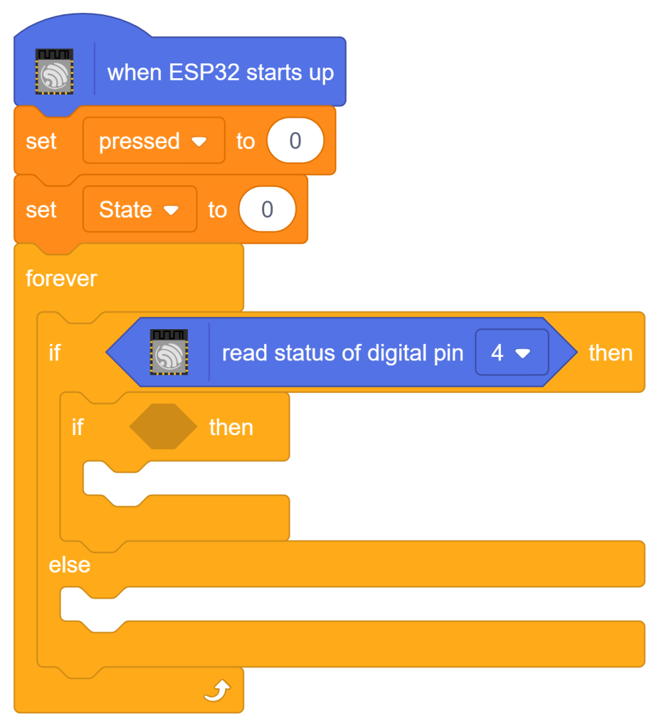
- Inside the newly added if condition, add the ‘equals to‘ block from the Operators palette.
- Add the pressed variable in the left side of ‘equals to‘ block. For the right side, set the value to ‘0‘.
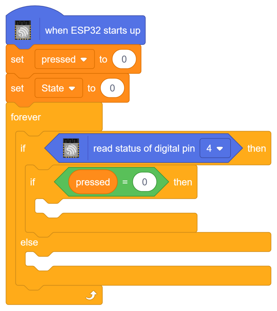
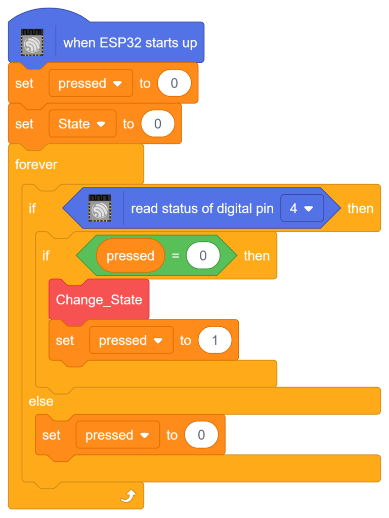
- Add the Change_State block from the My Blocks palette.
- Add the set () to () block from Control palette. Use the pressed variable and set its value to ‘1’
- Inside the else, add the set () to () block. Use the pressed variable and set its value to ‘0’.
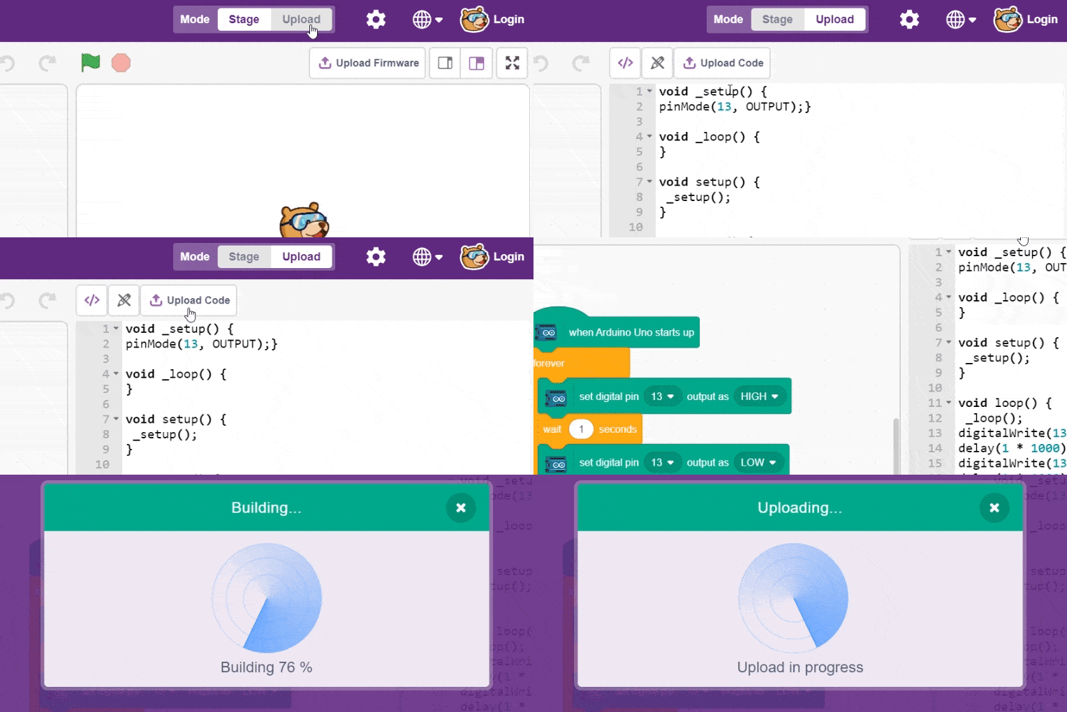
- To upload the code, click on the Upload Code button.
Output
Conclusion
In this lesson, we learned how to build a smart light switch by tracking variable states and interfacing a push button alongside an LED with the ESP32 board in PictoBlox’s Upload mode. We moved beyond simple direct polling by creating a custom function block to toggle the LED output on Pin 2 between HIGH and LOW based on the memory of our system variables. Through this hands-on project, you have gained practical experience with state-toggling logic—a vital tool you can now use to build advanced smart home systems and interactive automation projects!