



Introduction
Analog sensors are essential components found in everything from automatic night lights to temperature-controlled thermostats, allowing microcontrollers to understand the smooth, continuous changes of the real world! Learn what analog signals are, how Analog-to-Digital Converters (ADCs) transform varying voltage levels into readable data, how to interface analog sensors with evive, and program them with ease in PictoBlox – our Scratch blocks-based graphical programming platform with advanced hardware interaction abilities. Once you’re equipped with the basic knowledge of reading analog pin values, mapping raw data ranges, and setting output thresholds, we’ll show you how to monitor environmental changes and build exciting DIY smart sensing projects using the components available in the evive Starter Kit.
To work in PictoBlox, you’ll first need to download it from HERE.
Ready? Set. Go!
Prerequisites
- Evive Board
- Laptop or Computer
- PictoBlox installed on the system
- Analog Sensor – Light Dependent Resistor (LDR)
- Resistance
- Jumper Wires
How to connect evive with PictoBlox
- First, open PictoBlox.
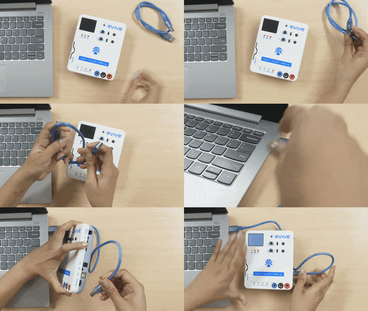
- Then, connect evive to your computer via a USB cable.
- Connect evive to your computer and open PictoBlox.
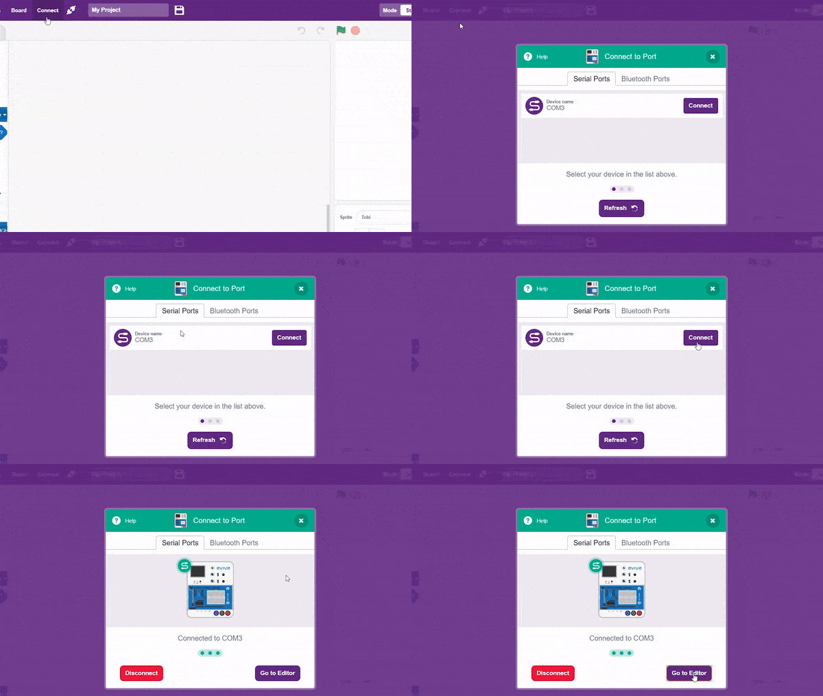
- In PictoBlox, go to the toolbar and click on the Board menu. Select Evive.
- Next, click on the Connect button, select the Port to which Evive is connected e.g. COMXX or ttyXX. Once you select the port, the icon beside the Connect tab will become connected.
- On the top right corner, there is a toggle button named Mode. This button is used to switch between the two working modes of PictoBlox, namely the stage mode and the upload mode.
- Switch to Upload mode by toggling this button. You’ll observe some changes in the UI.
How to interface the Analog Sensor
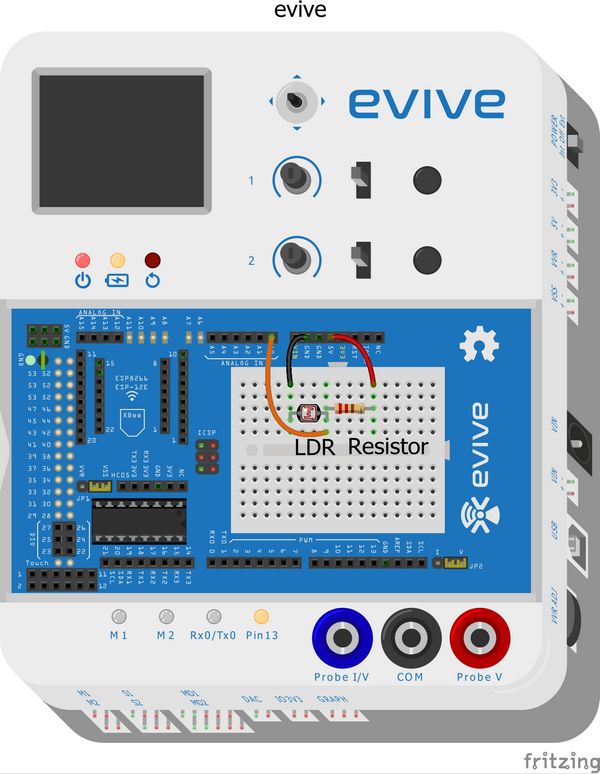
- Connect the LDR and 4.7k ohm resistor in series.
- Connect the 5V pin to the first leg of the LDR.
- Connect the ground pin to the end of the resistor.
- Connect the common leg of LDR and resistor to the A0 pin on evive.
Below is the complete circuit diagram:
Step-by-Step Block Coding Guide
- Go to the Evive palette and drag the ‘when Evive starts up’ block into the scripting area.
- Add the ‘fill screen with () color‘ block from Display palette. For the color choice use ‘Black‘.
- Add the ‘forever‘ block from Control palette.
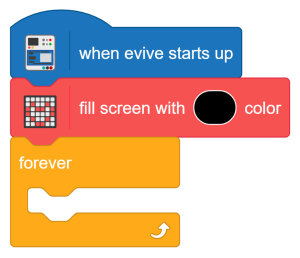 Go to Variables palette and Create a variable by clicking on Make a Variable button. Set the name as ‘Analog Reading’ as a number type.
- Go to Variables palette and Create another variable by clicking on Make a Variable button. Set the name as ‘Analog Voltage’ as a number type.
- Inside the ‘forever‘ block, add the ‘set () to ()‘ block from the Variables palette. Use the Analog Reading variable. For its value add the ‘read analog sensor () at ()’ block. Use the light/photoresistor as the Analog Sensor and set the pin at ‘A0‘.
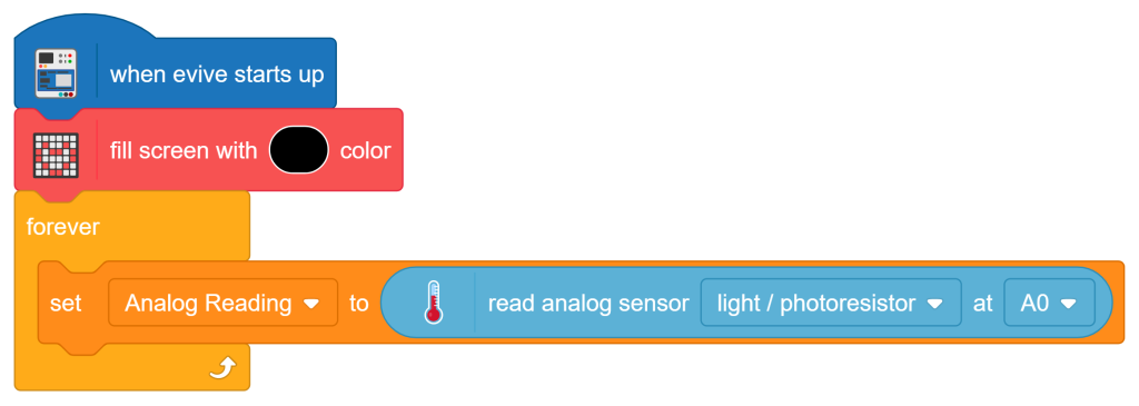
- Add another ‘set () to ()‘ block from the Variables palette. Use the Analog Voltage variable. For its value use the Formula:
Analog Voltage = (Analog Reading * 5) / 1023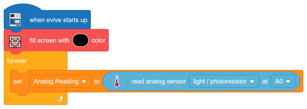
- Add the ‘set cursor at (), ()‘ block from the Display palette. Set the values as (10, 10).
- Add the ‘write ()‘ block from the Display palette. Inside the ‘write ()‘ block, add a ‘join ()‘ block from the Operators palette. In the first slot of the join block, type the text “Analog Reading: “. In the second slot of the ‘join ()‘ block, add another ‘join ()‘ block. Inside this second ‘join ()‘ block, place the ‘Analog Reading‘ variable from the Variables palette. Keep the second slot empty.
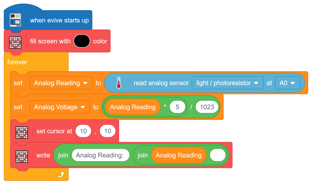 Add the ‘set cursor at (), ()‘ block from the Display palette. Set the values as (10, 20).
- Add the ‘write ()‘ block from the Display palette. Inside the ‘write ()‘ block, add a ‘join ()‘ block from the Operators palette. In the first slot of the join block, type the text “Voltage: “. In the second slot of the ‘join ()‘ block, add another ‘join ()‘ block. Inside this second ‘join ()‘ block, place the ‘Analog Voltage‘ variable from the Variables palette. In the second slot of the ‘join ()‘ block, type the text ‘V‘.
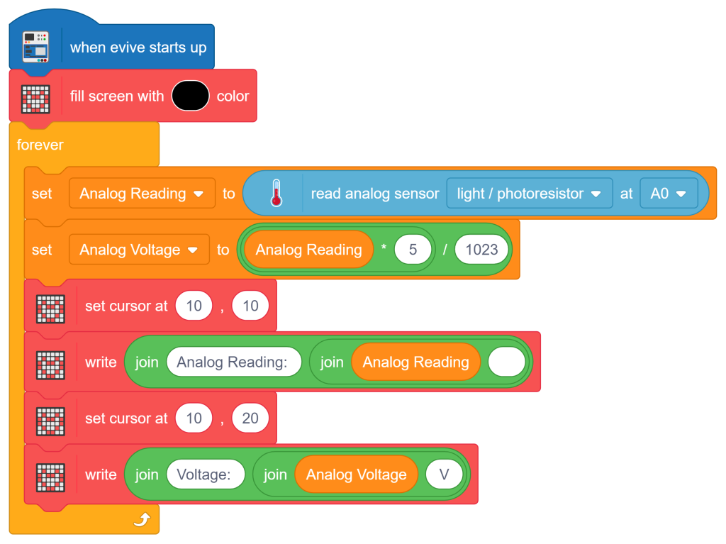
Now it’s time to upload the script to the Evive! For that, click on the Upload Code button, and voila!
Output
Conclusion
Conclusion
In this lesson, we learned what analog signals are and how microcontrollers use Analog-to-Digital Converters (ADCs) to make sense of the continuous variations in the physical world. We explored how to interface analog sensors with evive and write PictoBlox programs to continuously read raw voltage data, and map continuous input ranges. By working through these hands-on concepts, you have gained a solid foundation in processing real-world data and managing analog pin inputs.