



Introduction
Smartphones are packed with advanced internal sensors, but did you know you can use them as a massive wireless control deck for your electronics projects? By linking an ESP32 board directly to the Dabble app via its built-in Bluetooth, you can bypass complex hardware setups and transform your mobile device into a virtual treasury of endless controllers, switches, and shields! Once you’re equipped with the basic knowledge of wireless device pairing and mobile interface configuration, we’ll show you how to perform remote control on an ESP32 board using the Dabble app.
To work in PictoBlox, you’ll first need to download it from HERE.
Ready? Set. Go!
Prerequisites
- ESP32 Board
- Laptop or Computer
- PictoBlox installed on the system
- Smartphone
How to connect with ESP32
- First, open PictoBlox.
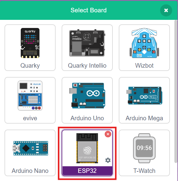
- Click on the Board tab on the toolbar and select ESP32.
- Next, click on the Connect button and select the appropriate serial port.
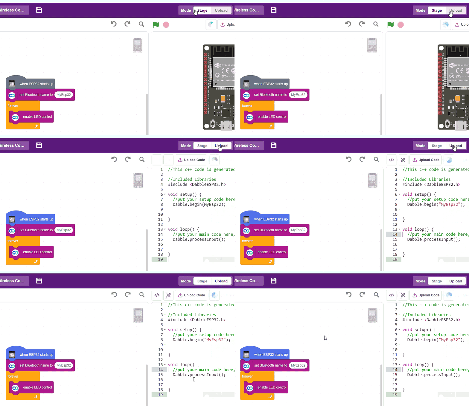
- In the top right corner, there is a toggle button named Mode. This button is used to switch between the two working modes of PictoBlox, namely the stage mode and the upload mode.
- Switch to Upload mode by toggling this button. You’ll observe some changes in the UI.
Step-by-Step Block Coding Guide
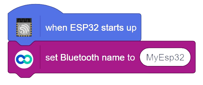
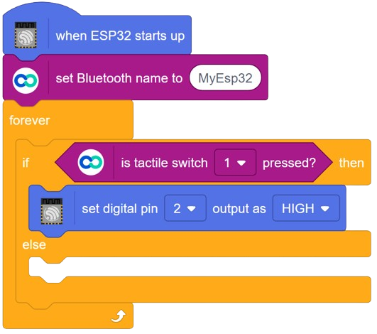
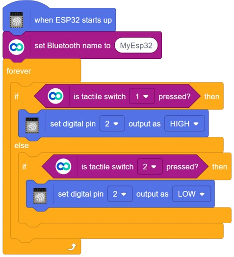
- Go to the ESP32 palette and drag the ‘when ESP32 starts up’ block into the scripting area.
- From the Dabble palette, add the ‘set Bluetooth name to ()’ block. Change its name to ‘MyESP32′.
- From the Control palette, add the ‘forever’ block.
- Add the ‘if () then else’ block inside the forever block from the Control palette.
- For the if condition, add ‘is tactile switch () pressed?’ block from the Dabble palette. Use switch ‘1′ here.
- From the ESP32 block, add the ‘set digital pin () output as ()’ block. Use digital pin ‘2′ and set its output as ‘HIGH’.
- Inside the else condition, add an ‘if () then’ block. For the if condition, add ‘is tactile switch () pressed?’ block from the Dabble palette. Use switch “2” here.
- From the ESP32 block, add the ‘set digital pin () output as ()’ block. Use Digital Pin “2” and set its output as “LOW”.
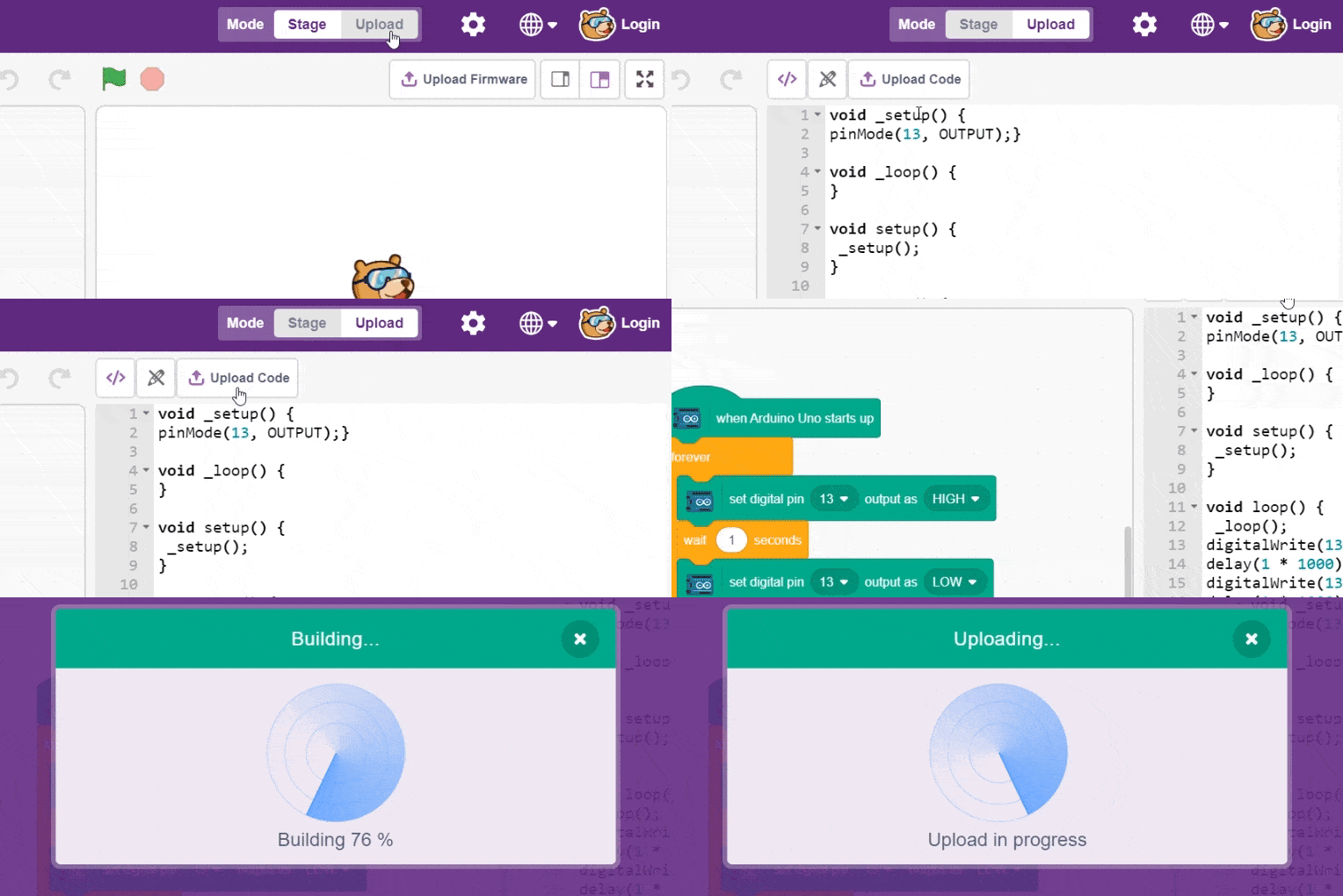
- To upload the code, click on the Upload Code button.
Pairing Dabble with ESP32
- Install the Dabble app from Play Store and open it on your smartphone.
- Next, click on the connect-disconnect icon.
- A dialogue box will appear on the screen asking for permission to turn on Bluetooth. Click on ‘Allow’.
- Once you do so, a list of nearby devices will appear. Select your device’s name.
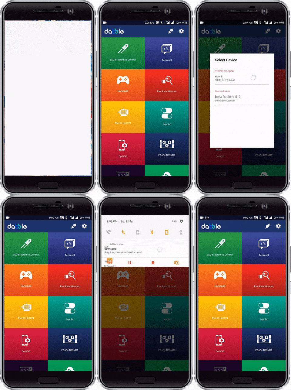
- In case you don’t see it on the list, go to the Bluetooth settings of your Smartphone and search for it there.
- A notification will appear in the drop-down menu of the phone once the connection is made.
- Once connected successfully, open the Inputs Module.
- The tactile switch is the third and last module in the input module. It senses whether the user has pressed on the switch or not. It is a momentary-type switch.
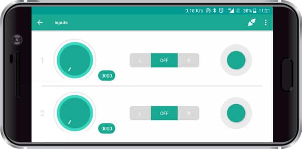
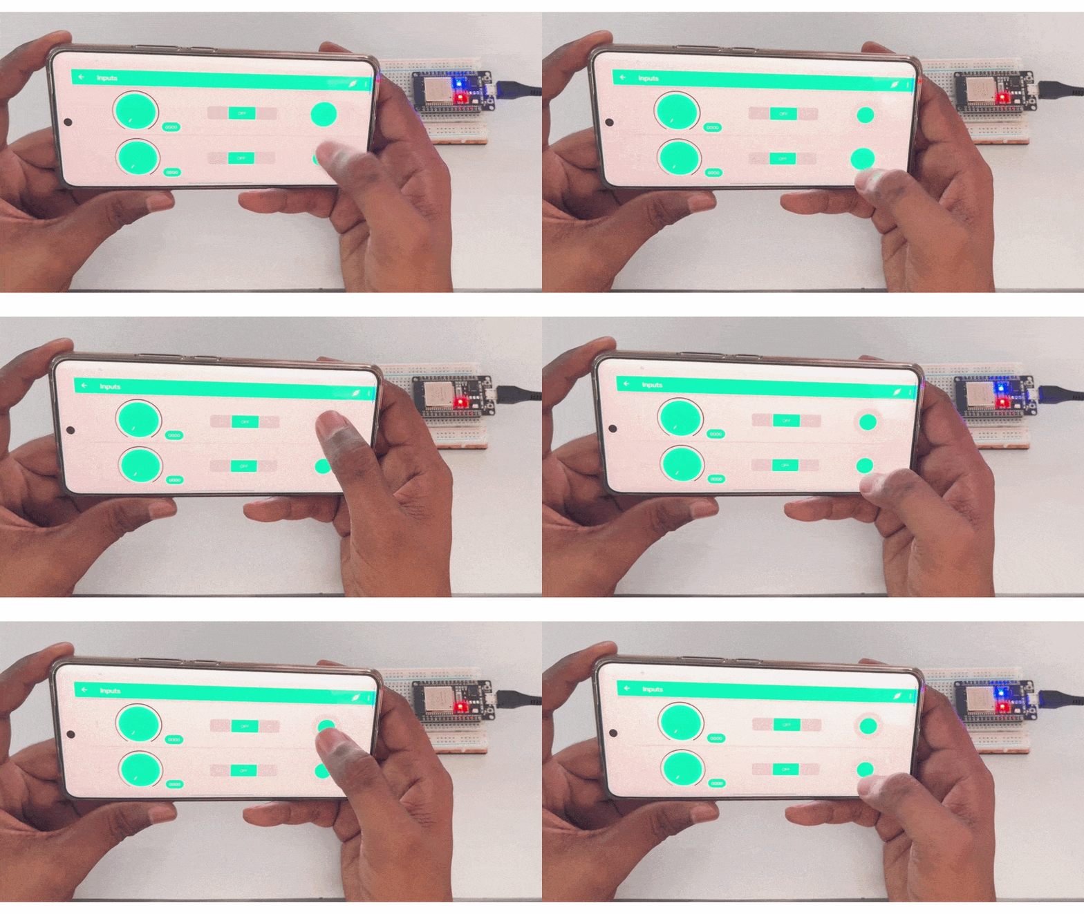
- Press the tactile switch and you will see the LED on the ESP32 turn ON and OFF according to the switch press.
Output
Conclusion
In this lesson, we explored how to interface the ESP32 board with the Dabble smartphone application using PictoBlox’s Upload mode. We learnt how to utilize the ESP32’s onboard Bluetooth functionality to establish a wireless link without needing any external communication modules. By using the specialised Dabble Input Module, we successfully created a user interface to continuously update the state of the built-in LED on the ESP32 board.