



Introduction
Switches are fundamental electronic components found in almost every electrical appliance we use daily, from simple wall switches to complex machinery control panels! Learn what a mechanical switch is, how input polling logic works, how to interface an LED and a switch with the ESP32 board, and program them with ease in PictoBlox – our blocks-based graphical programming platform with advanced hardware interaction abilities. Once you’re equipped with the basic knowledge of reading digital inputs, managing pull-up or pull-down resistor states, and handling hardware signals, we’ll show you how to securely control light sources and build exciting DIY smart home and automation projects using your ESP32.
To work in PictoBlox, you’ll first need to download it from HERE.
Ready? Set. Go!
Prerequisites
- ESP32 Board
- Laptop or Computer
- PictoBlox installed on the system
- Push Switch
How to connect with ESP32
- First, open PictoBlox.
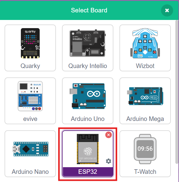
- Click on the Board tab on the toolbar and select ESP32.
- Next, click on the Connect button and select the appropriate serial port.
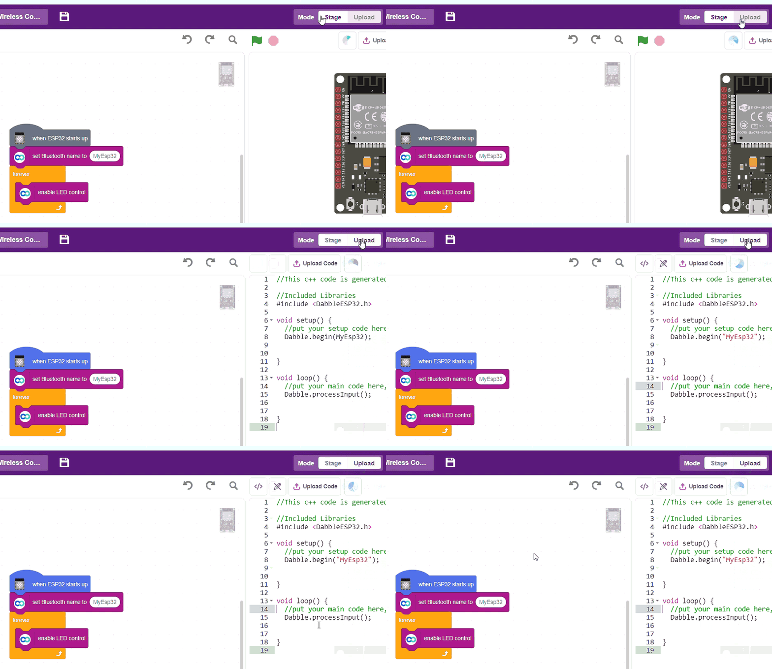
- In the top right corner, there is a toggle button named Mode. This button is used to switch between the two working modes of PictoBlox, namely the stage mode and the upload mode.
- Switch to Upload mode by toggling this button. You’ll observe some changes in the UI.
Connection Diagram
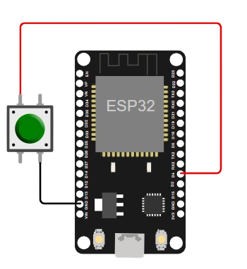
LED and Push Button Connection
- Connect the Ground Pin of the Push Button to GND in ESP32.
- Connect the Digital Input of the Push Button to PWM D4 Digital Pin in ESP32.
Step-by-Step Block Coding Guide
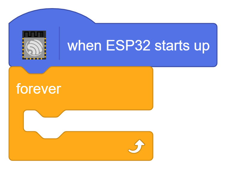
- Go to the ESP32 palette and drag the ‘when ESP32 starts up’ block into the scripting area.
- From the Control palette, add the ‘forever‘ block.
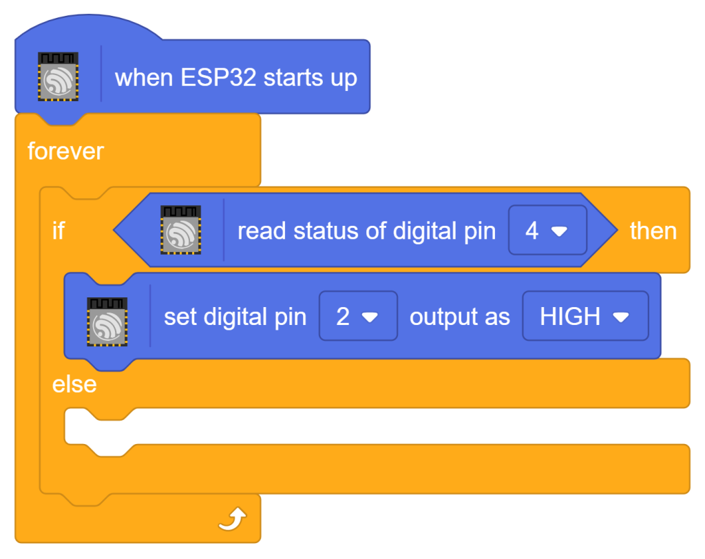
- From the Control palette, add the ‘if () then else’ block inside the ‘forever’ block.
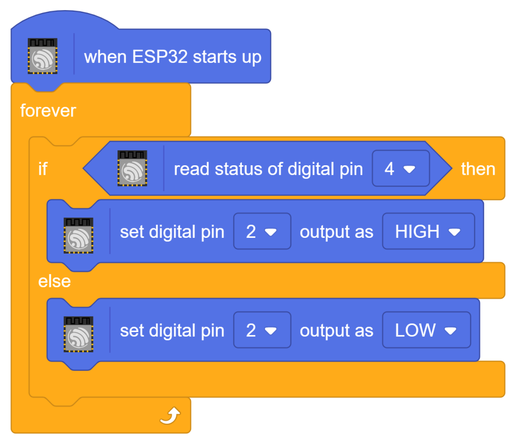
- From the ESP32 palette, add the ‘read status of digital pin ()‘ block. Use the digital pin ‘4‘.
- From the ESP32 palette, add the ‘set digital pin () output as ()’ block. Use the digital pin ‘2‘ and set its value to ‘HIGH‘.
- Inside the else, add the ‘set digital pin () output as ()’ block from ESP32 palette. Use the digital pin ‘2‘ and set its value to ‘HIGH‘.
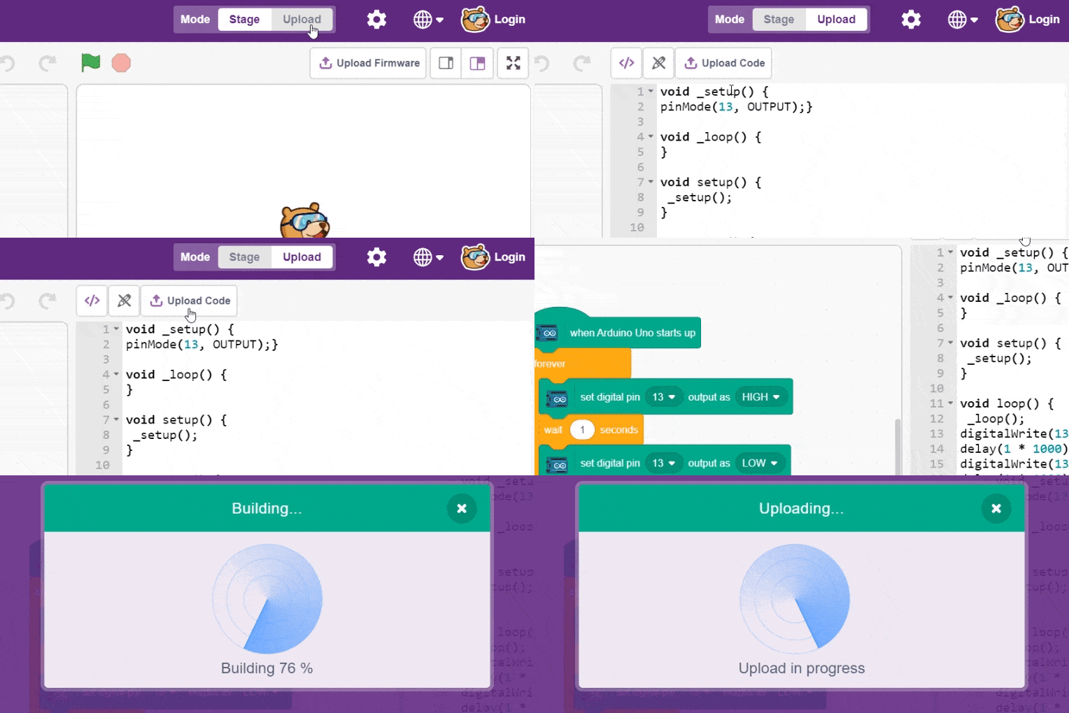
- To upload the code, click on the Upload Code button.
Output
Conclusion
In this lesson, we learned what a mechanical switch is, how to interface it alongside an LED with the ESP32 board, and how to program them using PictoBlox’s Upload mode. We explored fundamental input polling logic by writing a script that continuously reads the digital status of Pin 4 to control the output state of the onboard LED on Pin 2. Through this hands-on project, we gained practical experience in handling digital signals and understanding how hardware inputs drive real-time physical actions.