



Introduction
Voice activity is changing the way we interact with the world around us, bringing hands-free smart home automation right into our living spaces! Learn how speech recognition works, how to route voice inputs to your microcontrollers, how to interface an LED with the ESP32 board, and program it with ease in PictoBlox – our blocks-based graphical programming platform with advanced hardware interaction abilities. Once you’re equipped with the basic knowledge of processing voice commands, working with cloud-based speech recognition systems, and controlling digital outputs, we’ll show you how to build your very own smart lighting system and other exciting DIY voice-activated automation projects using your ESP32.
To work in PictoBlox, you’ll first need to download it from HERE.
Ready? Set. Go!
Prerequisites
- ESP32 Board
- Laptop or Computer
- PictoBlox installed on the system
- Smartphone
How to connect with ESP32
- First, open PictoBlox.
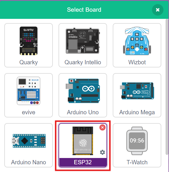
- Click on the Board tab on the toolbar and select ESP32.
- Next, click on the Connect button and select the appropriate serial port.
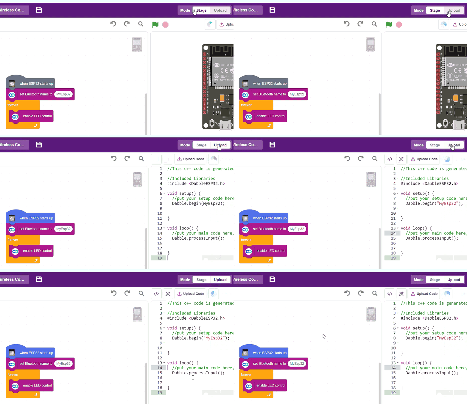
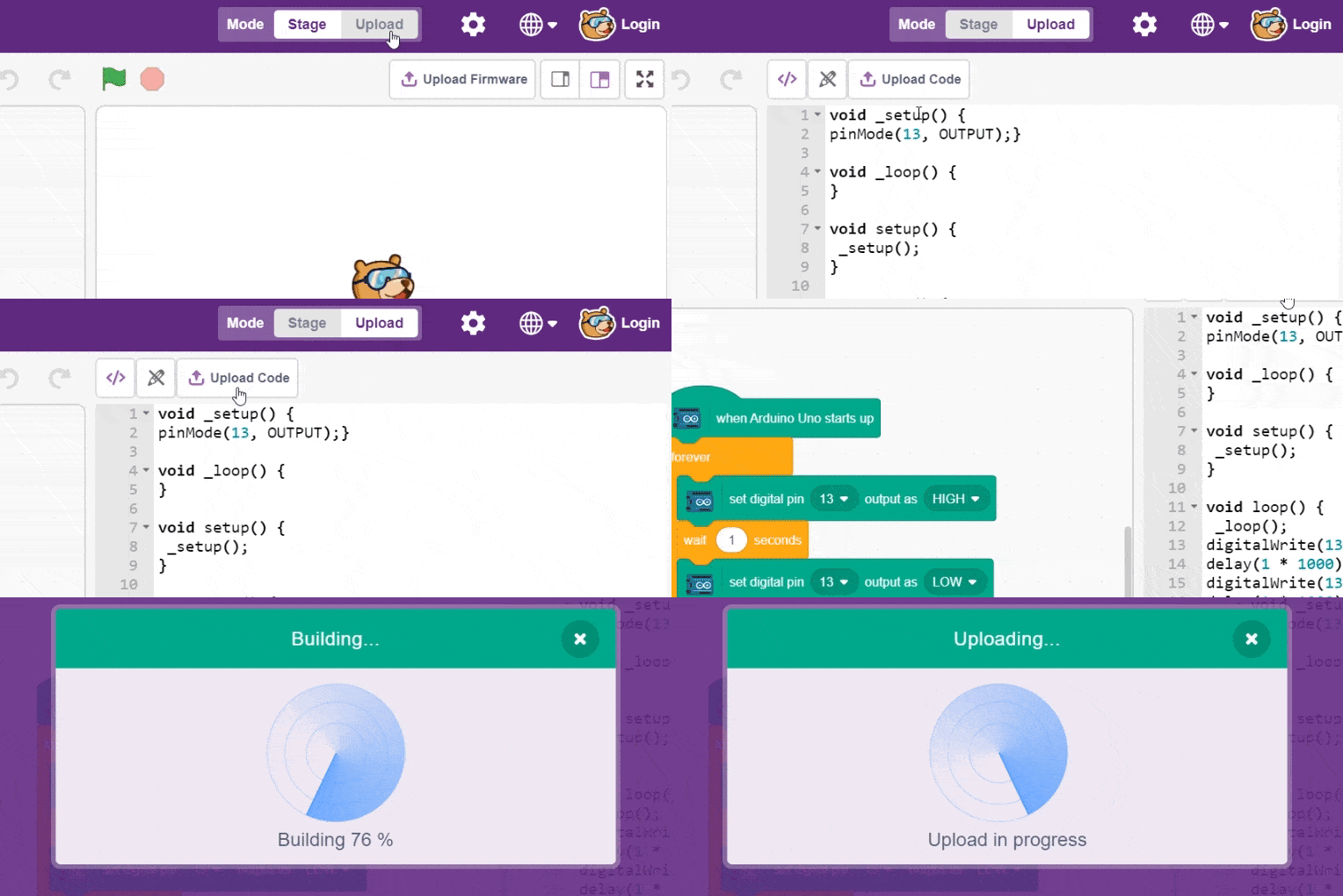
- In the top right corner, there is a toggle button named Mode. This button is used to switch between the two working modes of PictoBlox, namely the stage mode and the upload mode.
- Switch to Upload mode by toggling this button. You’ll observe some changes in the UI.
Step-by-Step Block Coding Guide
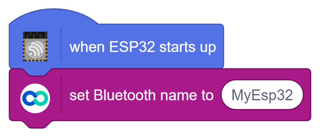
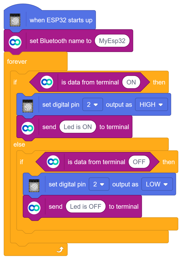
- Go to the ESP32 palette and drag the ‘when ESP32 starts up’ block into the scripting area.
- From the ESP32 palette, add the ‘set Bluetooth name to ()‘ block. Set its value to ‘MyEsp32‘.
- From the Control palette, add the ‘forever‘ block.
- Inside the ‘forever‘ block, add the ‘if () then else‘ block from the Control palette.
- Inside the if condition, add the ‘is data from terminal ()‘ block from the ESP32 palette. Set its value to ‘ON‘.
- Inside the if block, add the ‘set digital pin () output as ()‘ block from the ESP32 palette. Set the Pin to Digital PWM Pin ‘2‘ and set its value as ‘HIGH‘.
- Underneath the ‘set digital pin () output as ()’ block, add ‘send () to terminal‘ block from the ESP32 palette. Set its value to ‘Led is ON‘.
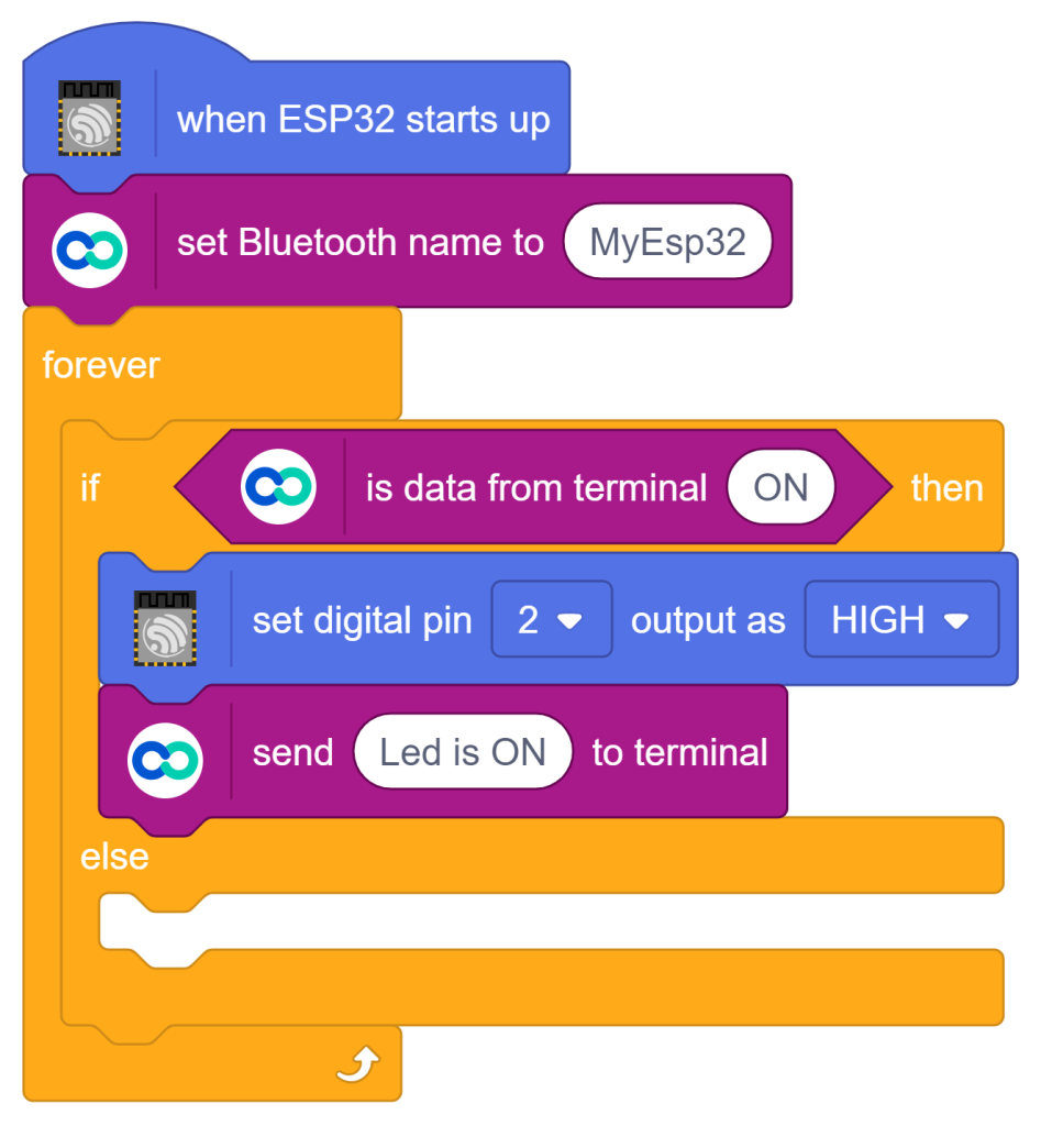
- Inside else, insert ‘if () then‘ block from the Control palette.
- Inside the if condition, add the ‘is data from terminal ()‘ block from the ESP32 palette. Set its value to ‘OFF‘.
- Inside the if block, add the ‘set digital pin () output as ()‘ block from the ESP32 palette. Set the Pin to Digital PWM Pin ‘2‘ and set its value as ‘LOW‘.
- Underneath the ‘set digital pin () output as ()’ block, add ‘send () to terminal‘ block from the ESP32 palette. Set its value to ‘Led is OFF‘.
- To upload the code, click on the Upload Code button.
Pairing Dabble with ESP32
- Install the Dabble app from Play Store and open it on your smartphone.
- Next, click on the connect-disconnect icon.
- A dialogue box will appear on the screen asking for permission to turn on Bluetooth. Click on ‘Allow’.
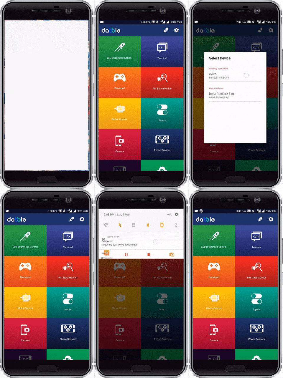
- Once you do so, a list of nearby devices will appear. Select your device’s name.You will find ‘MyEsp32‘ as the device to connect.
- In case you don’t see it on the list, go to the Bluetooth settings of your Smartphone and search for it there.
- A notification will appear in the drop-down menu of the phone once the connection is made.
- Once connected successfully, open the Terminal Module.
- Use the Google Speech provided in the interface, and provide the message as “ON” or “OFF” to control the LED on ESP32.
Output
Conclusion
In this lesson, we explored how to build a voice-controlled lighting system by interfacing an ESP32 board with the Dabble smartphone application. We learned how to utilize the onboard Bluetooth functionality of the ESP32 alongside Dabble’s Terminal module to capture spoken commands from a smartphone microphone. By writing conditional logic in PictoBlox’s Upload mode, we successfully programmed the ESP32 to analyze incoming voice data and toggle the state of a physical LED accordingly.