



Introduction
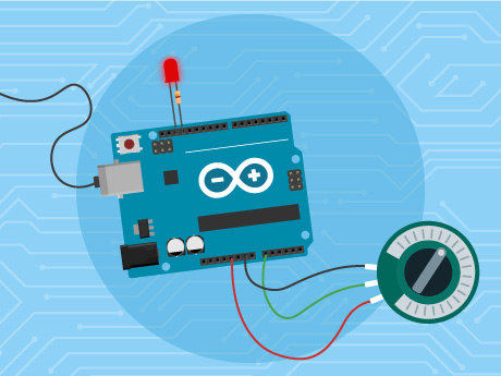
Pulse Width Modulation (PWM) is a technique used to control the brightness of LEDs by varying the amount of power supplied to them. In this project, a potentiometer is used as an input device to generate different analog values, which are then mapped to the LED brightness. This simple project helps learners understand analog input, PWM output, and basic sensor interfacing with Arduino.
Connections
LED
- Positive (Anode) → Digital Pin 3 (PWM) through a 220Ω resistor
- Negative (Cathode) → GND
Potentiometer
- One outer pin → 5V
- Other outer pin → GND
- Middle pin (Wiper) → A0
Step-by-Step Block Coding Guide
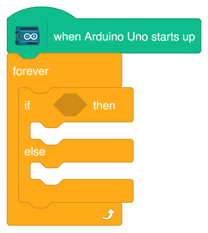
- Add the ‘When Arduino Uno Starts Up’ block.

- This block initializes the program and executes the code when the Arduino starts running.
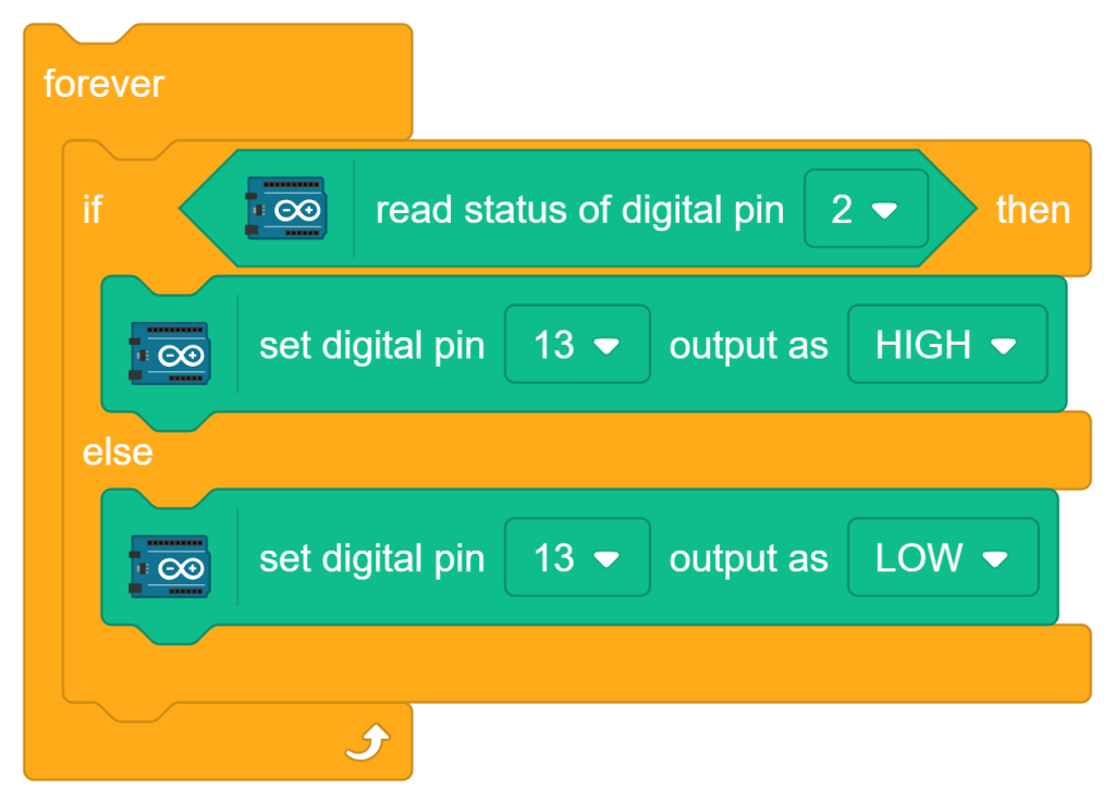
- Add a ‘Forever’ block below the start block.

- Inside the ‘forever’ block, add an ‘if-then-else’ conditional block.
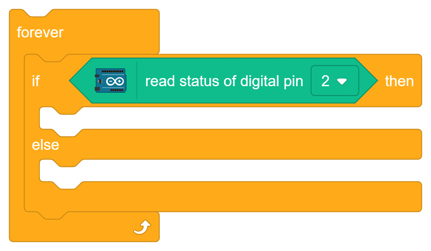
- In the ‘if’ condition field, insert the ‘read status of digital pin 2’ block.
- Inside the section, add the ‘set digital pin 13 output as HIGH’ block.
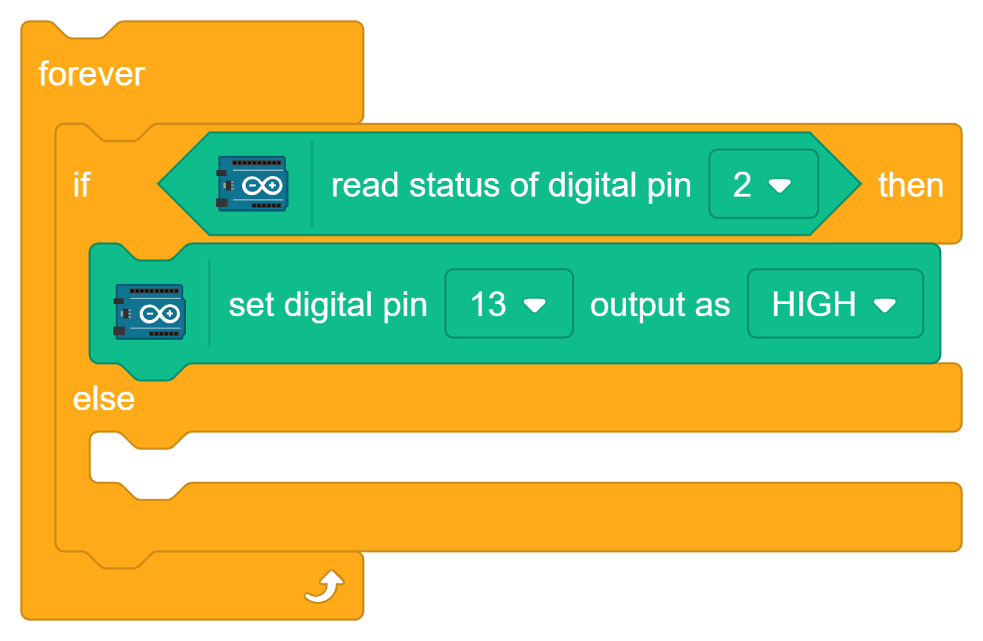
- Inside the ‘else’ section, add the ‘set digital pin 13 output as LOW’ block.
Conclusion
This project demonstrates how a potentiometer can be used to control LED brightness using Arduino Uno and PictoBlox. By combining analog input with PWM output, learners gain practical experience in sensor interfacing and output control. It serves as an excellent beginner project for understanding real-time interaction between hardware components and programming while introducing the fundamentals of embedded systems and automation.