



Introduction
Switches are commonly used in electronic devices to provide user input. In this activity, we will use a push button switch to control an LED connected to an Arduino board. Using PictoBlox block coding, students will learn how to read the state of a switch and control an output device based on the input received
Setting Up the Hardware
- Open PictoBlox
- create a new project in Block coding
- Keep the default sprite tobi on the stage
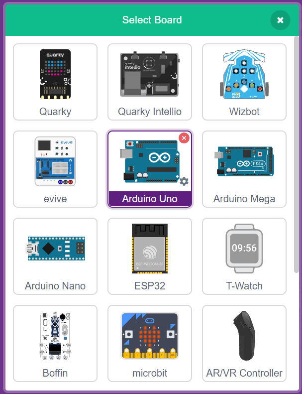
- Go for the board and select the board Arduino UNO
- Connect the Arduino board to the computer using a USB cable.
- Connect an LED to Digital Pin 13 of the Arduino.
- onnect a push button switch to Digital Pin 2 of the Arduino.
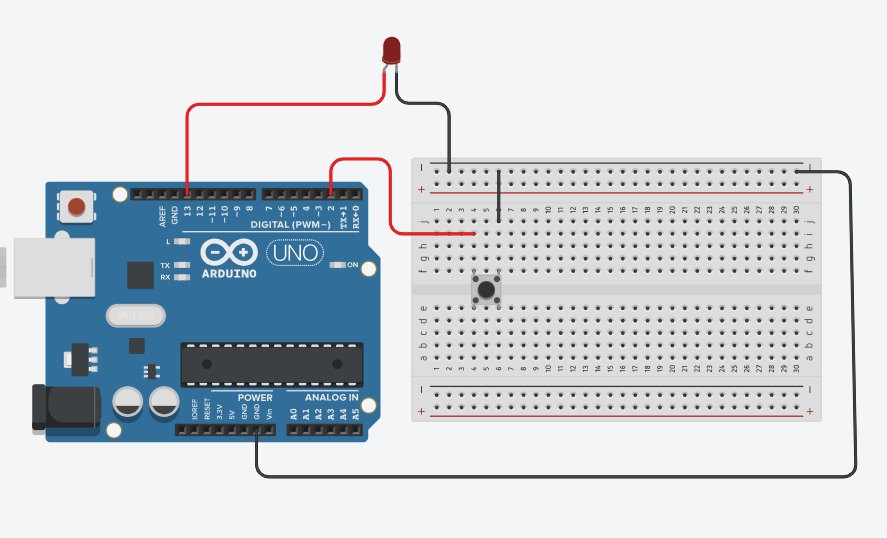
- Complete the circuit using appropriate jumper wires and a breadboard.
- Ensure all connections are secure before uploading the program.
Step-by-Step Block Coding Guide
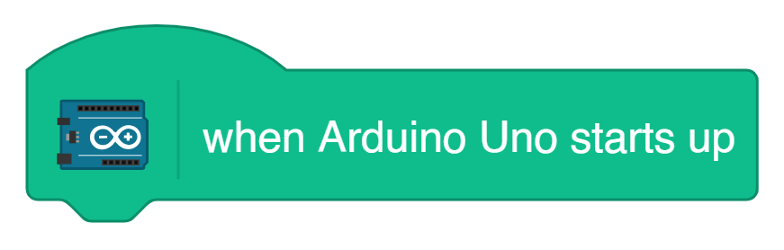
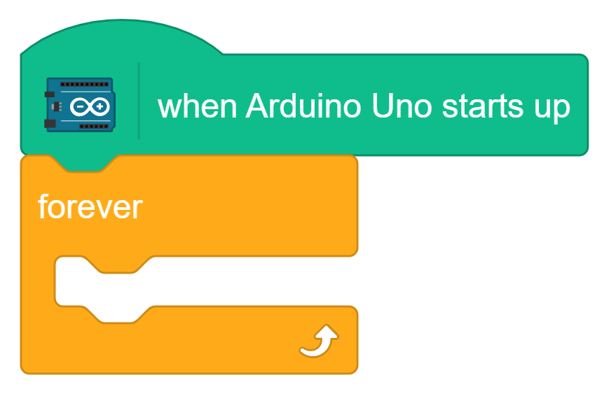
- Add the Arduino Start Block
- Add a Forever Loop from the control palette
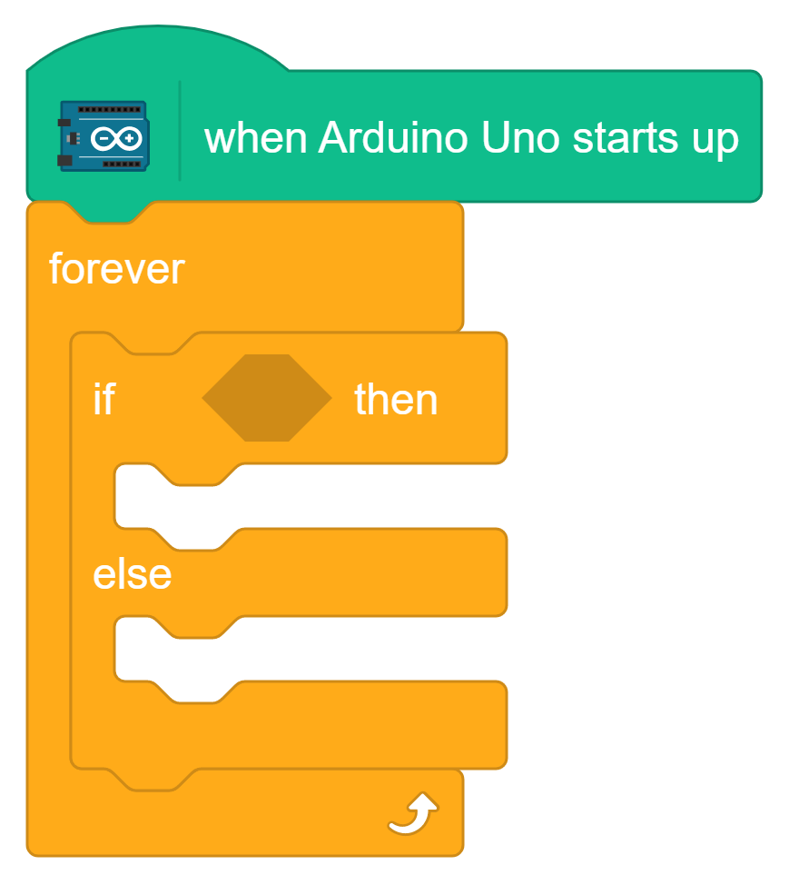
- Add the If-Else Block from the control pallet
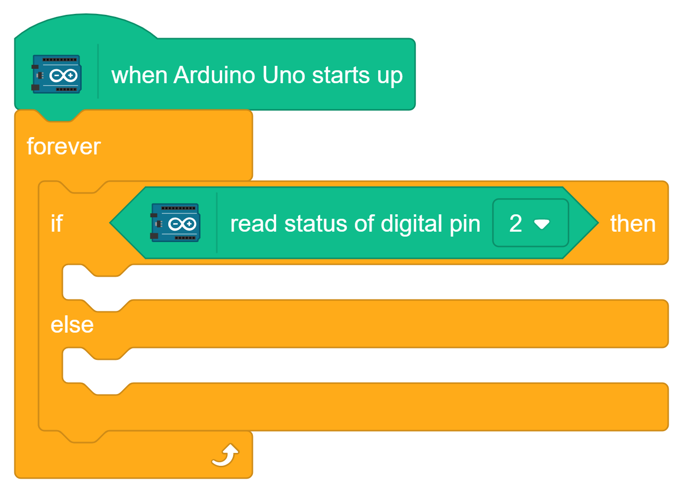
- From the Arduino category, drag the “read status of digital pin” block and set the pin number to 2. Place this block in the condition section of the if-else block.
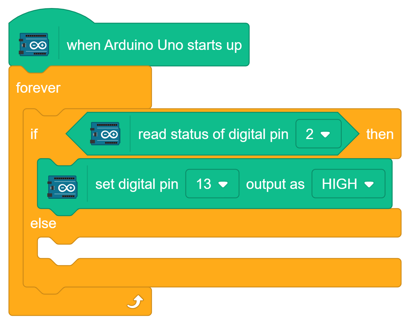
- From the Arduino category, drag the “set digital pin output as” block.
- Digital Pin – 13
- Output – High
When the switch is pressed, the LED connected to Pin 13 turns ON.
 6.Again from the Arduino category, drag the “set digital pin output as” block.
- Digital Pin – 13
- Output – LOW
When the switch is not pressed, the LED connected to Pin 13 turns OFF.
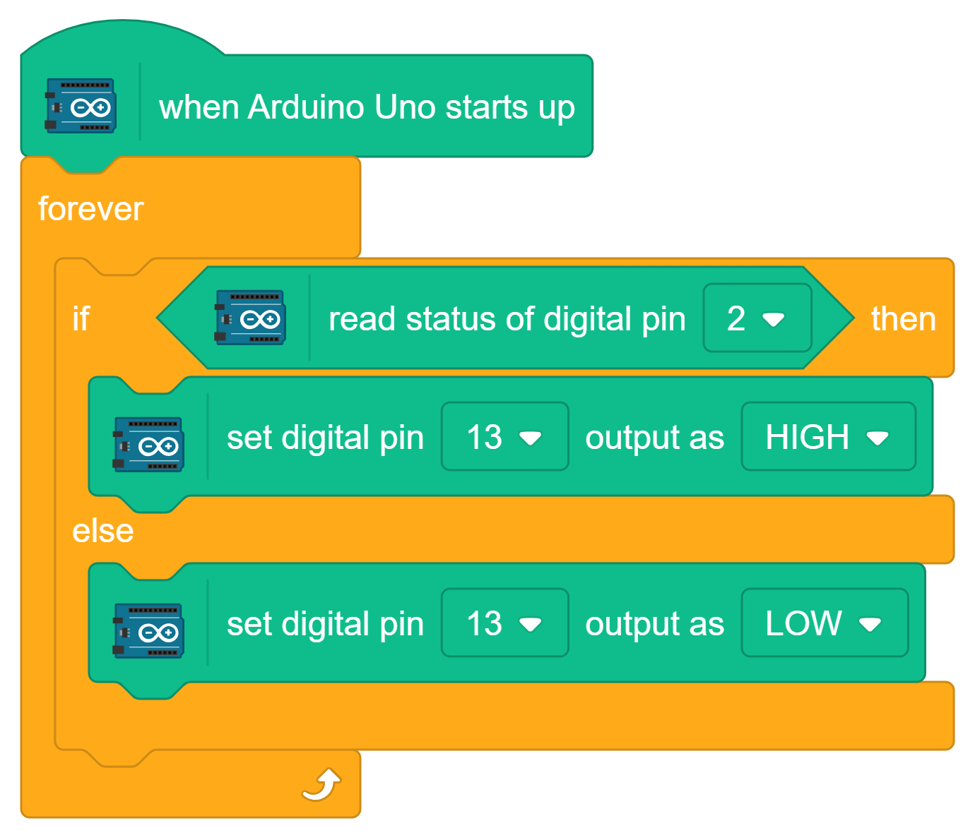 7.Connect the Arduino board to the computer and upload the block code.
- Press the switch to turn the LED ON.
- Release the switch to turn the LED OFF.
Conclusion
In this activity, we learned how to use a push-button switch as an input device and an LED as an output device. By reading the switch status and controlling the LED using block coding, we understood the basic concept of digital input and output in Arduino.