



Introduction
The Dabble Input Module allows users to send data into physical components connected to an Arduino board. This makes it possible to create interactive projects where actions in the real world control animations, games, and smart systems on the screen.
In this activity, we will connect a Smartphone to Arduino and use Dabble to detect the button press. Based on the button pressed, you will find the LED changing its state to ON or OFF. To work in PictoBlox, you’ll first need to download it from HERE.
Ready? Set. Go!
Prerequisites
- Arduino Uno R3 Board
- 220Ω Resistor
- Breadboard
- LED
- Laptop or Computer
- PictoBlox installed on the system
- Jumper Wires
- Smarphone
How to Connect with Arduino Uno
- Connect Uno to your computer and open PictoBlox.
- In PictoBlox, go to the toolbar and click on the Board menu. Select Arduino Uno.
- Next, click on the Connect button, select the Port to which Arduino Uno is connected e.g. COMXX or ttyXX. Once you select the port, the icon beside the Connect tab will become connected.
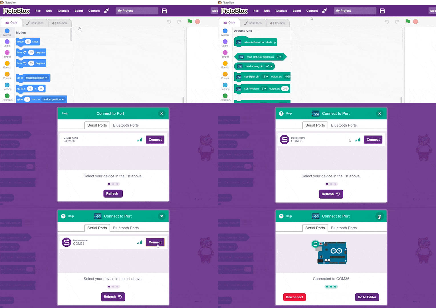
- On the top right corner, there is a toggle button named Mode. This button is used to switch between the two working modes of PictoBlox, namely the stage mode and the upload mode.
- Switch to Upload mode by toggling this button. You’ll observe some changes in the UI.
Circuit Connections
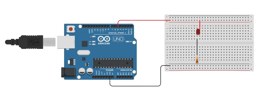
LED Connection
- Connect the longer leg (Anode) of the LED to Digital PWM Pin 5 through a 220Ω resistor.
- Connect the shorter leg (Cathode) of the LED to GND.
- Connect Arduino GND to the breadboard’s negative rail.
Step-by-Step Block Coding Guide
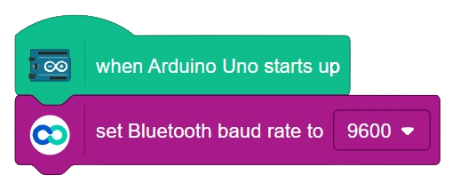
- Go to the Arduino Uno palette and drag the ‘when Arduino Uno starts up‘ block into the scripting area.
- From the Dabble palette, add the ‘set Bluetooth baud rate to ()‘ block. Set its value to ‘9600‘.
- From the Control palette, add the ‘forever’ block.
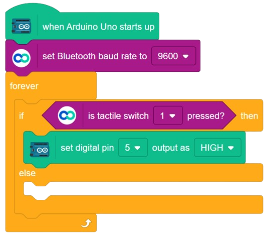
- Inside the ‘forever‘ block add one ‘if () then else’ block from the Control palette.
- Inside the if condition, add the ‘is tactile switch () pressed ?‘ block from the Dabble palette. Set its value to 1.
- From the Arduino Uno palette, add the ‘set digital pin () output as ()‘. Set the digital pin as 5 and output as HIGH.
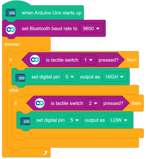
- Inside the else condition, add one ‘if () else‘ block from Control palette.
- Inside the if condition, add the ‘is tactile switch () pressed ?‘ block from the Dabble palette. Set its value to 2.
- From the Arduino Uno palette, add the ‘set digital pin () output as ()‘. Set the digital pin as 5 and output as LOW.
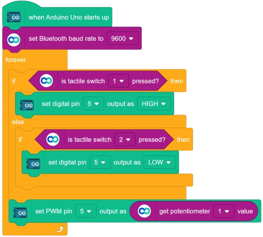
- Finally, at the end of ‘if () then else‘ block, add the ‘set PWM pin () output as ()‘ block. Set the pin value as 5 and add the ‘get potentiometer () value‘ from Dabble palette as the Output. Set the potentiometer value as 1.
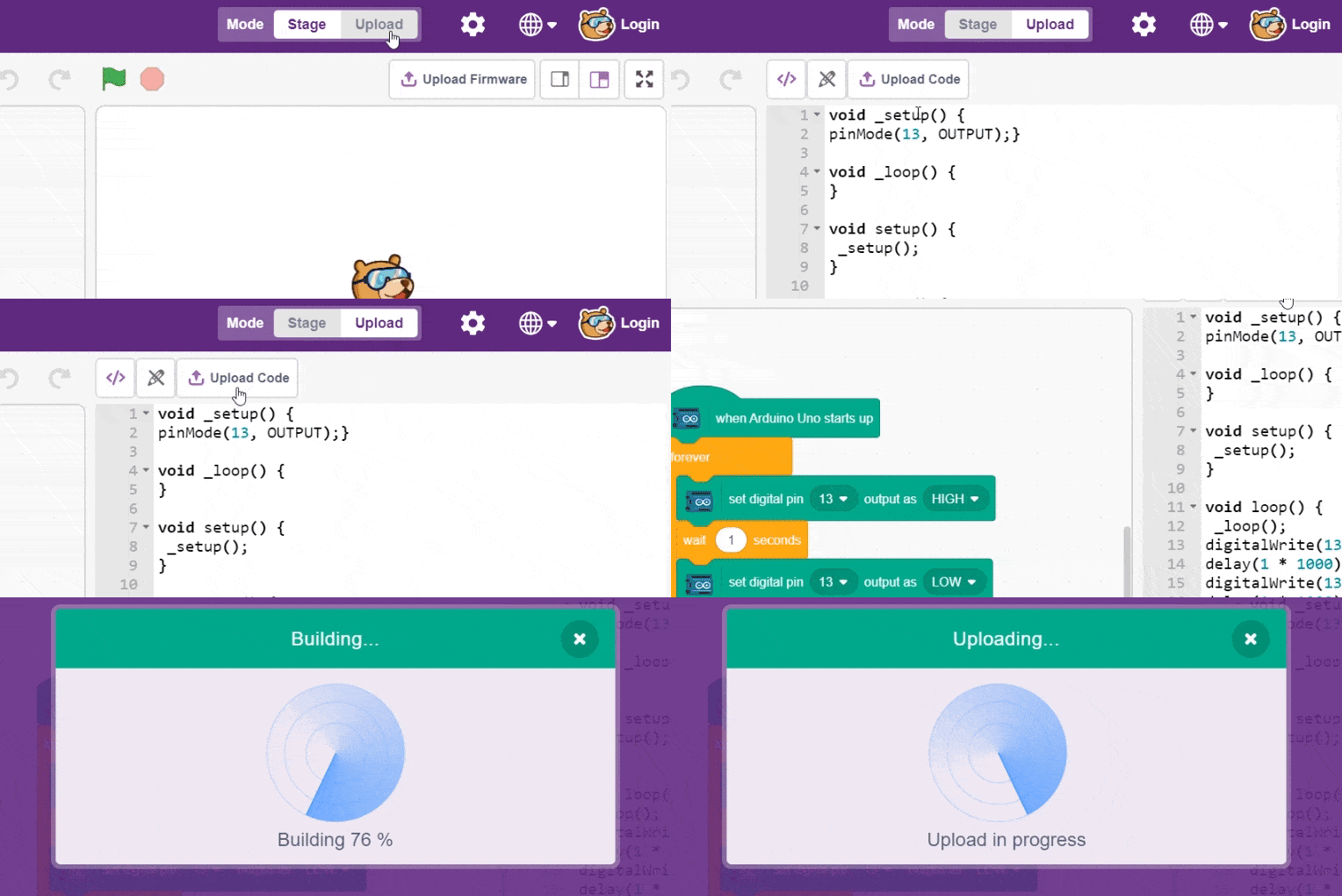
- To upload the code, click on the Upload Code button.
Pairing Dabble with Uno
- Install Dabble from Play Store and open it on your Smartphone.
- Next, click on the connect-disconnect icon.
- A dialogue box will appear on the screen asking for permission to turn on Bluetooth. Click on ‘Allow’.
- Once you do so, a list of nearby devices will appear. Select your device’s name.

- In case you don’t see it on the list, go to the Bluetooth settings of your Smartphone and search for it there.
- If your Smartphone asks for a password to pair it with the device, enter the default password. For HC-05 and HC-06, it is 0000 or 1234. For HM-10 it is 000000 or 123456.
- A notification will appear in the drop-down menu of the phone once the connection is made.
- Now, open the Inputs module and you’re ready to go.
Output
Conclusion
The Arduino Phone Sensor Reader extension enables smartphones to act as powerful sensor input devices for Arduino projects. By accessing real-time orientation data, users can create interactive physical computing applications without additional hardware sensors. This project demonstrates how mobile technology can be integrated with Arduino and PictoBlox to build engaging and responsive systems. The same concept can be expanded to control robots, games, smart devices, and IoT applications using smartphone sensor data.