Table of Contents

map () from () () to () ()

Description

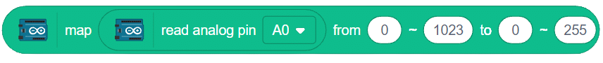
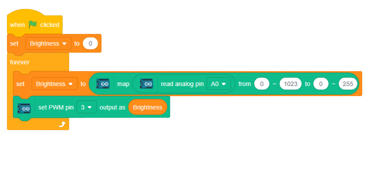
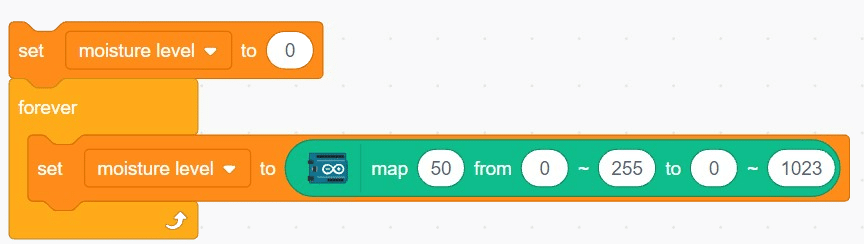
The block maps the specified value from the first range to the second range.

Example

Learn about soil moisture sensors and how they work to measure the moisture level in the soil.
introduction

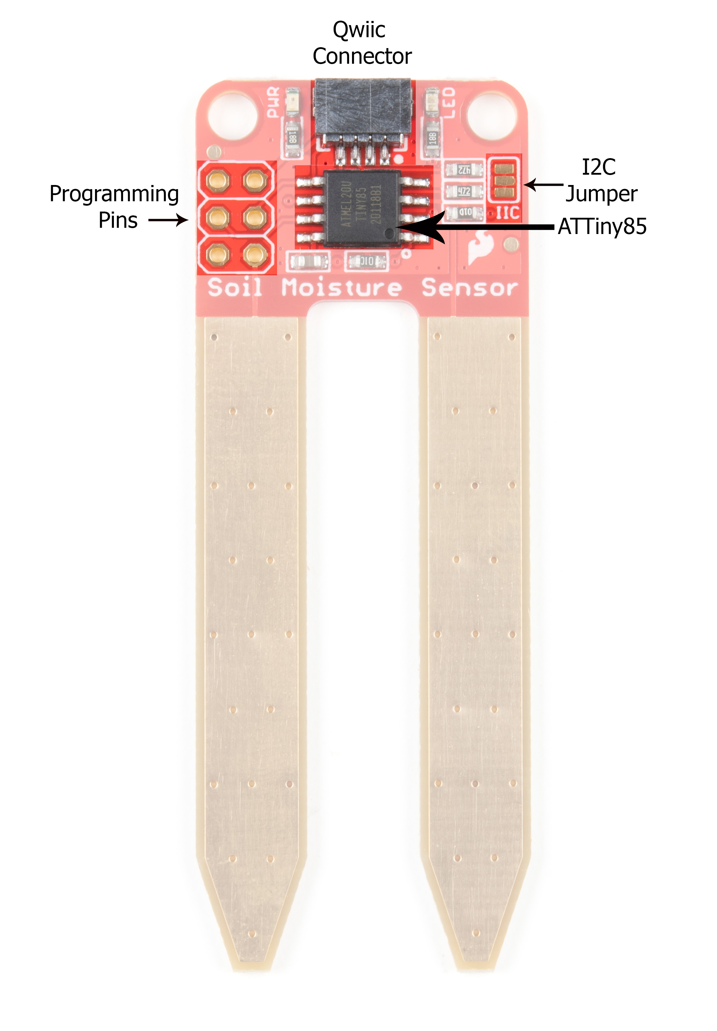
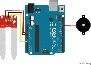
The soil moisture sensor is a valuable tool used to determine the moisture content in the soil, crucial for efficient gardening, farming, and agricultural practices. This analog sensor generates varying output values depending on the moisture level present in the soil. Typically, it operates as a two-pin circuit, with these pins responsible for powering up the sensor module. To obtain soil moisture readings, a voltage divider circuit is employed on the negative pin of the sensor, resulting in a signal pin that provides the moisture level data. Alternatively, some sensor modules come with a controller circuit that automatically converts the 2-pin connection into a 3-pin output, simplifying the process of accessing moisture values.

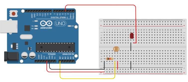
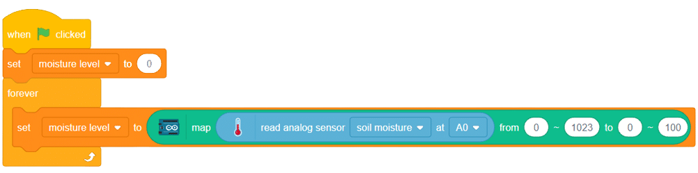
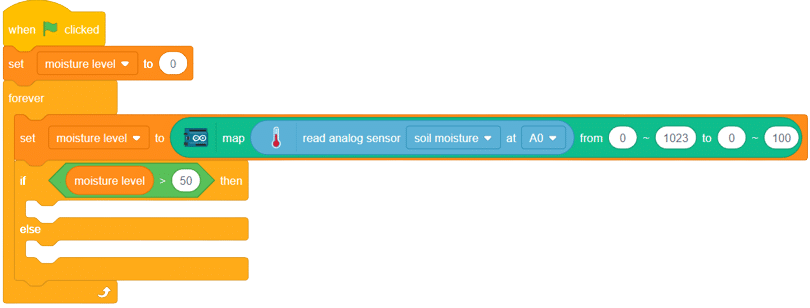
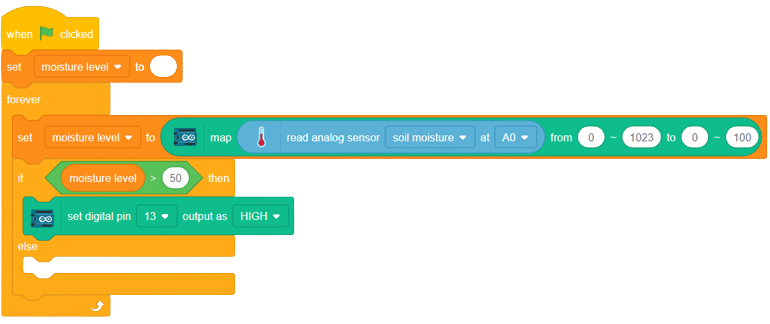
Below is a simple circuit diagram and code to get you started with monitoring soil moisture using an Arduino board. By following these steps, you can create your own moisture monitoring system with ease. Let’s begin!


Soil Moisture Sensor Hookup Guide - SparkFun LearnAuslese™ Detection Module Soil Moisture Sensor (Pack of 1Pcs) : Amazon.in: Industrial & Scientific

circuit diagram

Code

  1. Goto my variables and create a variable and name it “moisture level.” Set its initial value to 0.
  2. Add a “forever” loop from the control palette..
  3. Inside the forever loop, add a “set () to ()” block using the “my variable” category. Set the variable “moisture level” to the output value of the next block.
  4. From the Arduino palette, add the “map () from ()-() to ()-()” block. Replace the placeholder “0” with the map block.
  5. From the sensor palette, insert the “read analog sensor () at ()” block in place of “50”, and change the data range from 0-1023 to 0-100, also add “when flag clicked” at the start of the script, from event palette. As shown below.
  6. Add an “if-else” block from the controls palette. Use it to check whether the value of the sensor greater than 50% or not.
  7. If the value is greater than 50%, activate the buzzer connected to pin 13.
  8. And if the value if less then 50% then the buzzer must remain OFF.

Script

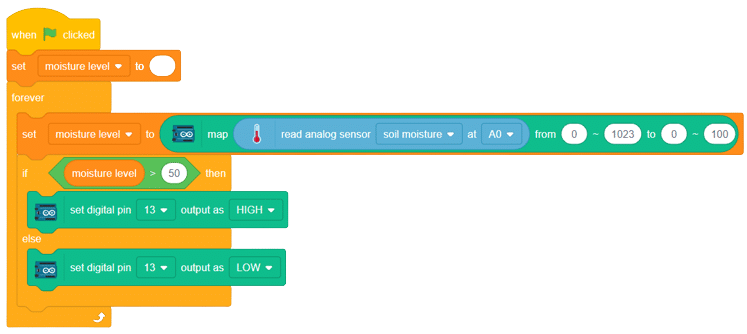
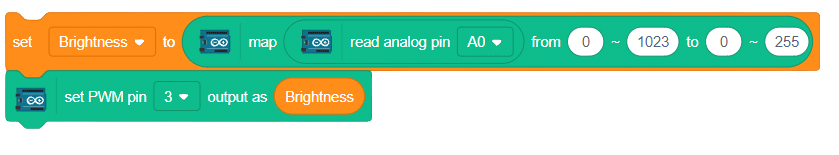
With these steps, your script is complete, and you can now monitor the soil moisture effectively using the soil moisture sensor and Arduino board. Happy gardening and farming!

Output


Read More
Learn about potentiometers, their working principle, and applications as variable resistors or voltage dividers.

Potentiometer and It’s working

A potentiometer is a versatile three-terminal resistor that forms an adjustable voltage divider or variable resistor (rheostat). It consists of two terminals connected to a resistive element and a third terminal connected to an adjustable wiper. The potentiometer can vary the amount of resistance in the circuit based on the wiper’s position.

Circuit Diagram

Code

  1. Create a variable called “brightness” and set it to 0.
  2. Add the “forever” block from the control palette.
  3. Use the “map” block from the Arduino palette to convert the range of values (0-1023) to the desired range (0-255) for brightness control. Read the values from Arduino pin A0 and place them in the first space of the map function.
  4. Set the brightness variable to the mapped value using the “set brightness to” block.
  5. Use any PWM pin of the Arduino to connect an LED.
  6. Set the PWM value to the brightness variable.
  7. Add these two blocks inside the forever block.
  8. Finally, add when flag clicked event to complete the script.

Script

Output

Read More
All articles loaded
No more articles to load