Introduction
A gesture-controlled robotic arm is a robotic arm that can be controlled using hand or body movements instead of traditional buttons or joysticks. It uses sensors and algorithms to interpret the gestures made by a user and translates them into commands for the robotic arm.
The user wears or holds a device with sensors, such as a glove or wristband, that captures their hand movements or body gestures. These movements are processed by a computer or microcontroller, which analyzes them and recognizes specific gestures using algorithms and machine learning techniques.
Once the gestures are recognized, the system generates commands for the robotic arm to move accordingly. The arm can have multiple joints and degrees of freedom to perform complex movements. The user’s gestures are mimicked by the robotic arm, allowing them to control its actions.
Gesture-controlled robotic arms are used in various fields, including manufacturing, healthcare, and virtual reality. They provide a more intuitive and natural way of controlling robotic systems, eliminating the need for complex input devices and extensive training.
Hand Gesture Classifier Workflow
Follow the steps below:
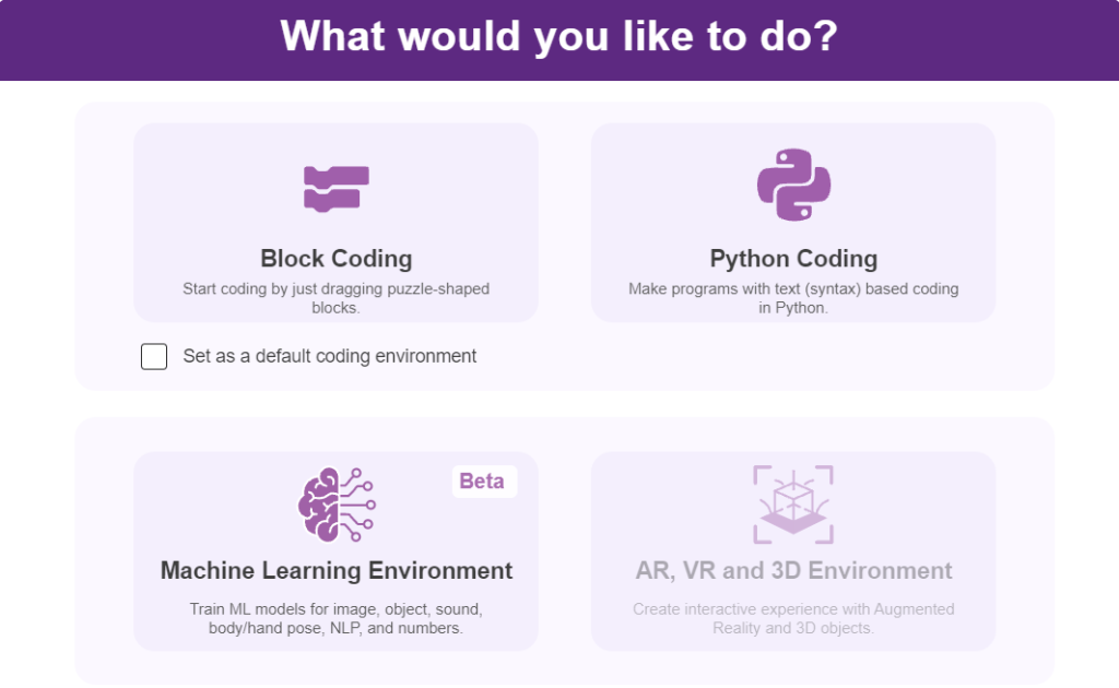
- Open PictoBlox and create a new file.
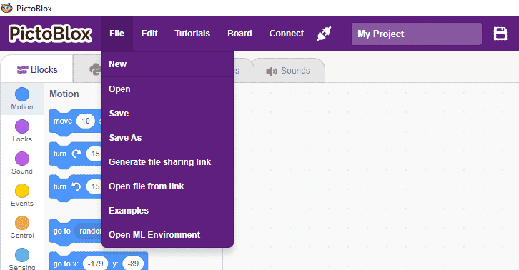
- Select the coding environment as appropriate Coding Environment. you can click on “Machine Learning Environment” to open it.
- Select the “Open ML Environment” option under the “Files” tab to access the ML Environment.
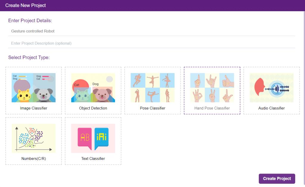
- Click on “Create New Project“.
- A window will open. Type in a project name of your choice and select the “Hand Gesture Classifier” extension. Click the “Create Project” button to open the Hand Pose Classifier window.
- You shall see the Classifier workflow with two classes already made for you. Your environment is all set. Now it’s time to upload the data.
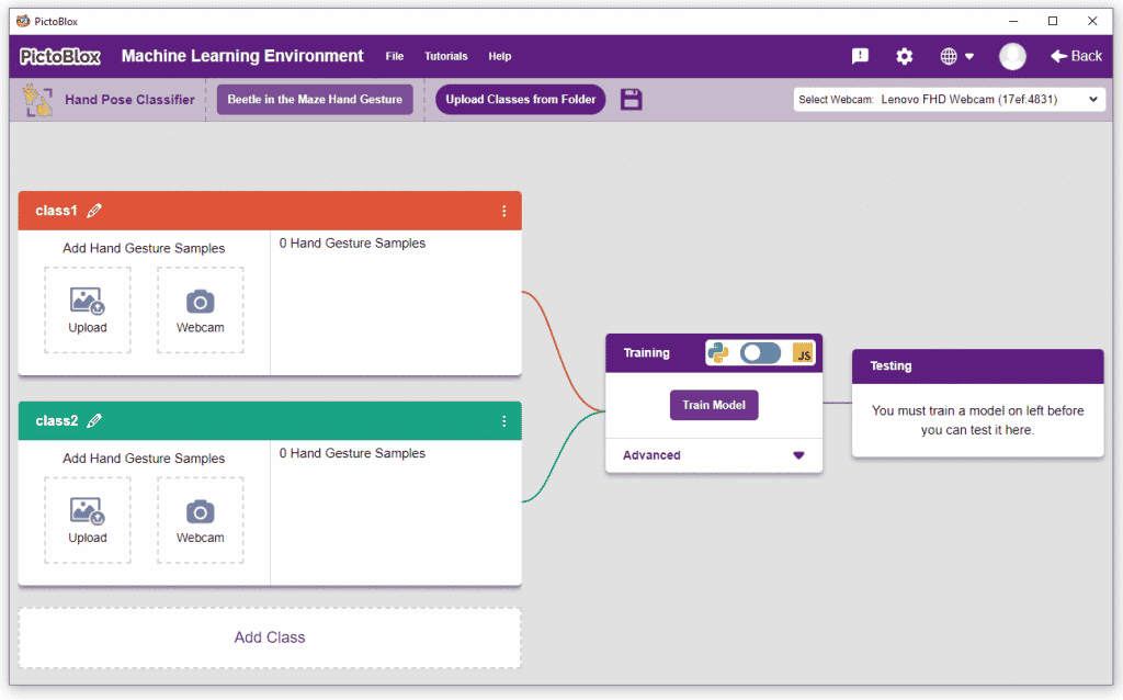
Class in Hand Gesture Classifier
There are 2 things that you have to provide in a class:
- Class Name: The name to which the class will be referred.
- Hand Pose Data: This data can be taken from the webcam or uploaded from local storage.

Note: You can add more classes to the projects using the Add Class button.
Adding Data to Class
You can perform the following operations to manipulate the data into a class.
- Naming the Class: You can rename the class by clicking on the edit button.
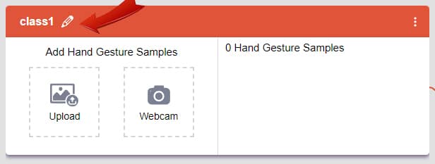
- Adding Data to the Class: You can add the data using the Webcam or by Uploading the files from the local folder.
- Webcam:
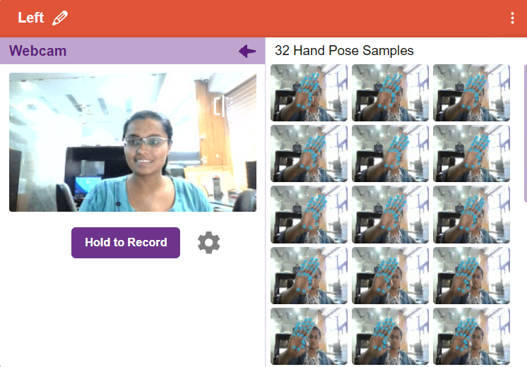
Note: You must add at least 20 samples to each of your classes for your model to train. More samples will lead to better results.
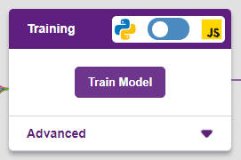
Training the Model
After data is added, it’s fit to be used in model training. To do this, we have to train the model. By training the model, we extract meaningful information from the hand pose, and that in turn updates the weights. Once these weights are saved, we can use our model to predict previously unseen data.
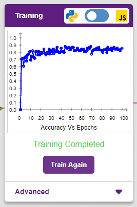
The accuracy of the model should increase over time. The x-axis of the graph shows the epochs, and the y-axis represents the accuracy at the corresponding epoch. Remember, the higher the reading in the accuracy graph, the better the model. The range of accuracy is 0 to 1.
Testing the Model
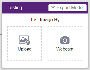
To test the model, simply enter the input values in the “Testing” panel and click on the “Predict” button.
The model will return the probability of the input belonging to the classes.
Export in Block Coding
Click on the “Export Model” button on the top right of the Testing box, and PictoBlox will load your model into the Block Coding Environment if you have opened the ML Environment in the Block Coding.
Logic
The robotic arm will move according to the following logic:
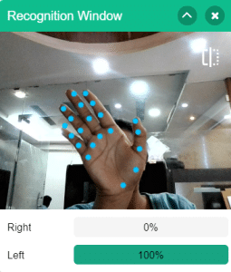
- When the left gesture is detected – the robotic arm will move in the anti-clockwise direction.
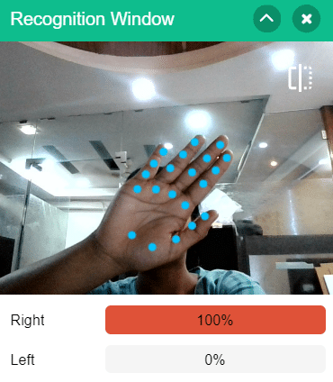
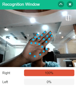
- When the right gesture is detected – the robotic arm will move in a Clockwise direction.
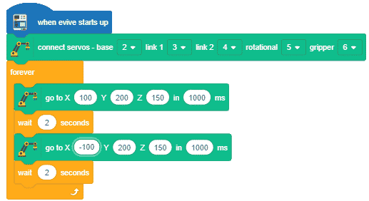
Code
Logic
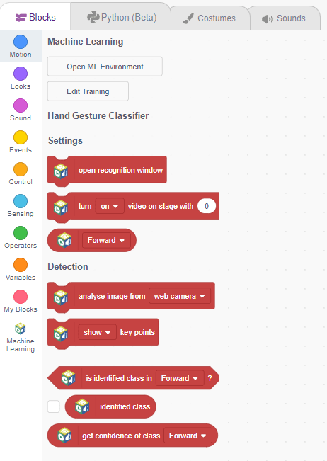
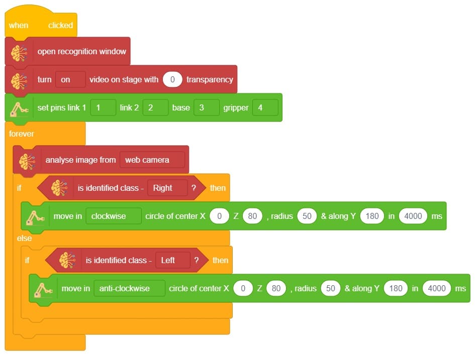
- First we Initialize Robitc Arm extension.
- Then, we open the recognition window, which will identify different poses, and turn on the camera with a certain level of transparency to identify images from the stage.
- If the identified class is “left,” the Robotic arm will move in anti-clockwise direction using move in () circle of center X() Z(),radius() & along Y() in ()ms block.
- If the identified class is “right,” the Robotic Arm will move right using move in () circle of center X() Z(),radius() & along Y() in ()ms block
- Press Run to run the code.
Output