


Introduction
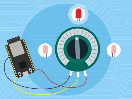
The ESP32 LED Brightness Control project is a simple and interactive electronics project that demonstrates how analog input and PWM technology can be used to control the brightness of an LED. In this project, the ESP32 microcontroller is programmed using PictoBlox block coding to create a smart LED brightness control system. The ESP32 reads analog values from a potentiometer and adjusts the LED brightness accordingly in real time.
When the ESP32 starts, it continuously reads the analog input from the potentiometer connected to the board. Based on the input value, the ESP32 generates a PWM (Pulse Width Modulation) signal to control the intensity of the LED. By rotating the potentiometer, users can smoothly increase or decrease the brightness of the LED without using fixed switches. This project helps beginners understand the basics of ESP32 programming, analog input reading, PWM output control, and real-time automation systems. It also introduces students to embedded systems and smart lighting concepts in an easy and practical way using graphical programming.
Prerequisites
Step 1
- ESP32
- PictoBlox Software (Desktop )
Connecting Your ESP32 to Pictoblox Blocks
Step 2
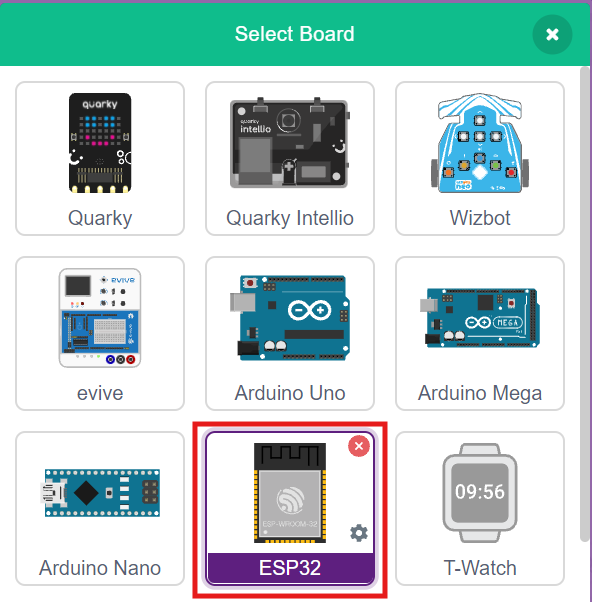
- Click on the Board tab on the top navigation bar and select ESP32.
- Now, click on connect.
- Select your ESP32 from the Serial port list and click on Connect.
- ESP32 plays a confirmation sound on connecting.
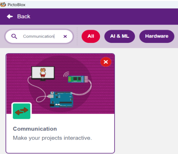
Step 3: Add the Communication Extension
Click on the Extensions button and add the Communication extension. This Communication Extension in PictoBlox is used to enable wireless and wired communication between devices, computers, and microcontrollers. This extension allows users to connect hardware such as ESP32, Arduino, Quarky, and other supported boards to exchange data and control devices in real time. It plays an important role in IoT and smart automation projects.
Using the Communication Extension, students can create projects that involve Bluetooth communication, Wi-Fi communication, serial communication, and cloud-based data transfer. The extension provides easy-to-use blocks that help beginners understand communication concepts without writing complex code.
- To run this project correctly, change the mode from Stage Mode to Upload Mode in PictoBlox. Upload Mode is used to upload the block code directly into the ESP32 board.
- After changing the mode, connect the ESP32 board to the computer using a USB cable and upload the program.
- Once the code is uploaded, the ESP32 will continuously read the analog values from the potentiometer and control the LED brightness using PWM.
- By rotating the potentiometer, the LED brightness will increase or decrease smoothly in real time.
Block-by-Block Guide
Step 5: Upload the code
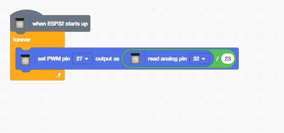
- Add the ‘When ESP32 starts up’ block – The program starts automatically when the ESP32 board is powered ON.
- ‘Read analog pin 32’ – This block continuously reads the analog value from the potentiometer connected to GPIO pin 32 on the ESP32 board.
- Drag the ‘Forever’ block from Control palette – The blocks inside this loop run continuously without stopping.
- Add ‘set PWM pin 27 output’ – This block continuously adjusts the PWM output value on GPIO pin 27 based on the analog input received from the potentiometer, allowing smooth control of LED brightness in real time.
Output
Conclusion
In this project, we used PictoBlox block coding to create an LED Brightness Control system using the ESP32 board. The blocks used in this project include when ESP32 starts up, read analog pin, forever, and set PWM pin output. These blocks help continuously read analog values from a potentiometer and control the brightness of an LED in real time using PWM technology. By changing the potentiometer position, the LED brightness smoothly increases or decreases, helping users understand analog input reading, PWM control, and real-time hardware interaction using the ESP32.