




Introduction
Casper was the first DIY humanoid robot that we built. But all it could do was speak with its eyes, and it moved around on wheels. Today, we’re going to build another humanoid robot that is not only as expressive as Casper but can also dance, move around, and give you a hi-5 among other things! And it’s super cute! All the components that you need to make it are available in the Humanoid Robot Kit and you can easily program it in PictoBlox, our smart graphical programming software.
Prerequisites
- Evive(charged and powered on)
- USB cable
- PictoBlox installed on a Wi-Fi connected device
- Firmware uploaded to evive via the Upload Firmware button in PictoBlox
- Note: Before connecting Evive to PictoBlox, ensure that the Arduino/CH340 device driver is installed properly.
Connecting Evive to PictoBlox.
- First, open PictoBlox.
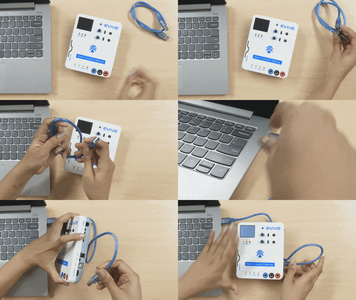
- Then, connect Evive to your computer via a USB cable.
- Click on the Board button in the toolbar. A list of the boards that are compatible with PictoBlox will appear in the drop-down. Select evive from the option.
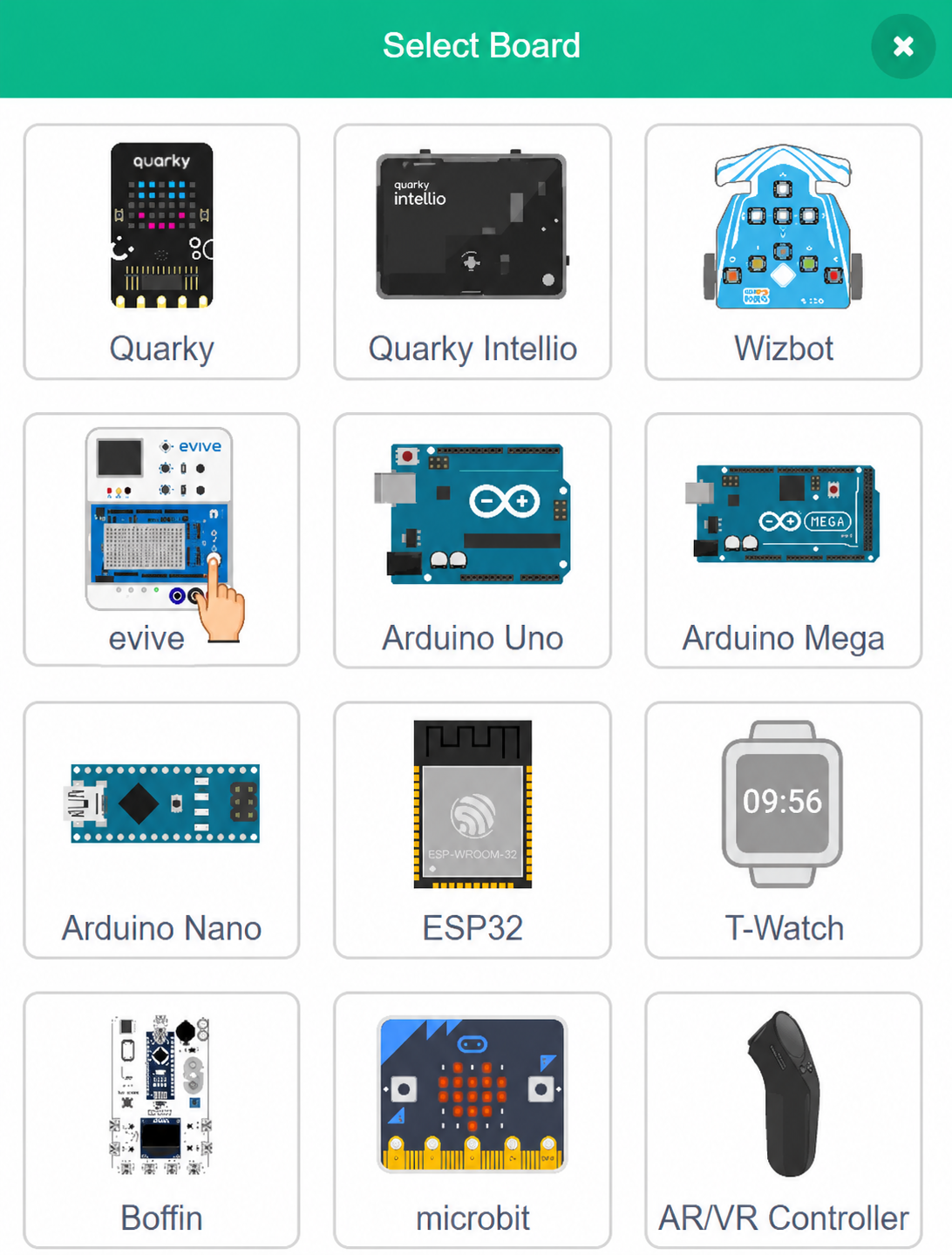
- Select evive from the drop-down. Next, click on the connect button and select the appropriate serial port.You’ll notice new palettes under the Code tab. You can interact with evive using the blocks in these palettes.
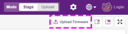
Since we’re going to work in Stage mode, we must upload the firmware to the board. It will ensure real-time communication between the board and the computer. Uploading the firmware is a one-time process. To do so, click on the Upload Firmware button. Observe that while doing so, the Rx0/Tx0 LED starts blinking.
To check whether the firmware has been successfully uploaded or not, observe evive’s screen. If evive’s logo appears on the screen, it indicates success. Otherwise, retry the process.
Step-by-Step Assembly Guide
1. Assembling the Base of the Humanoid Robot
Let’s start the assembly by making the base so that all the rest of the body parts will be attached. Take the body base plate and attach two metal servos to the space given using M4 bolts and nuts. One for the left leg and another for the right leg.
Before you attach the servos, set the servo angle to 90 degrees for all the six servos using evive.
Calibration of the servo has never been this easy. Connect the metal servo to either of the servo channels. Switch ON evive, you notice a menu on the TFT screen. This is evive’s firmware. Select Controls, select Servos, then select the Servo channel on which the servo is connected. Then, using the corresponding potentiometer, set the servo angle to 90°.
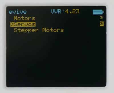
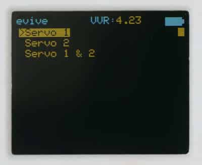
Once done, take the leg servo horn plates and attach the two-sided servo horn to them using servo screws.
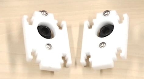
Now attach the leg servo horn plates to the body base plate by mounting the servo horns to the servo heads using servo bolts.
2. Assembling the Legs
Now, let’s start the assembly of the leg.
We are going to see the detailed making of one leg. The making of the other leg will be exactly the same as the first one. Make sure that the servo head should point downwards.
- Take the leg back servo plate and attach a metal servo to it using M4 nuts and bolts.
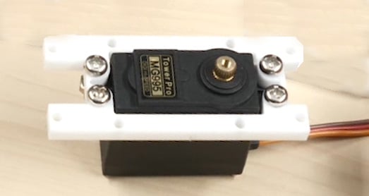
- Next, take the leg-side and attach them to the leg-back servo plate using M3 bolts of length 12mm and M3 nuts.
- Next, take the leg bottom plate and attach it to the leg side plates using M3 bolts of length 12mm and M3 nuts.
- Then, take the leg front plate and screw the M4 bolt and nuts to it in the hole given in the center.
- Now, fix this leg front plate to the leg side plates using M3 bolts of length 12mm and M3 nuts. Make sure that the slot given for the wire to pass is close to the body base plate.
- Repeat steps 1 to 4 for the other leg
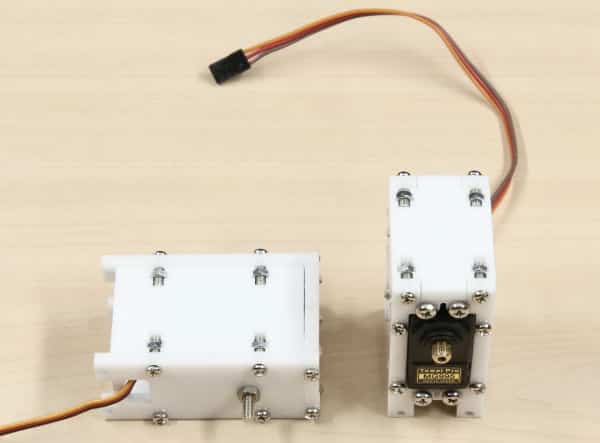
- Once both the leg-sub assemblies are ready, fix them to the leg servo horn plate by using four M3 nuts and bolts.
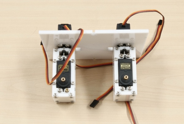
With this, the leg assembly of our bipedal robot is complete. Let’s move forward to the making of the feet of the bipedal.
3. Assembling the Feet of the Bipedal
Let’s begin with the feet assembly.
Similar to the above step, we are going to make one foot in detail. And the other foot will just be similar to the first one.
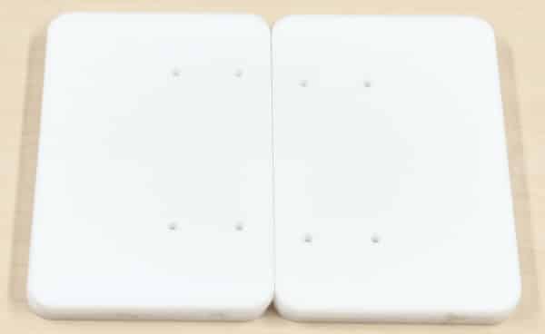
- Take the foot base and glue it to the foot sole. Keep it aside to dry.
- Till then, take the foot servo horn plate and attach a two-sided servo horn to it using servo screws.
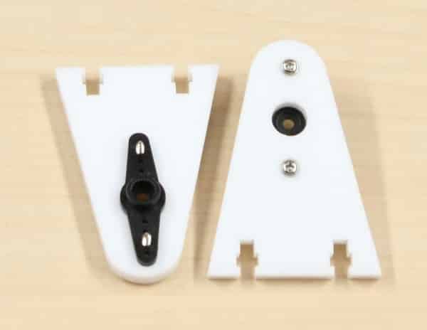
- Next, place the servo horn plate and foot front plate on the foot base and attach it using M3 bolts of 12mm length and M3 nuts.
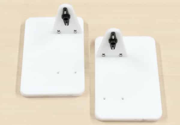
- Repeat steps 1 to 3 for the other side of the foot, too.
- Finally, we are going to fix the feet assemblies to the leg assembly by attaching the servo horn to the servo using servo screws. And fix the foot front plate to the leg assembly using M4 bolts and M4 lock nuts. This will give movement to the feet of the robot. The lower body of our humanoid is complete. It’s time to make the upper body.
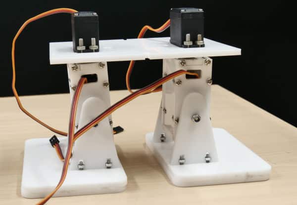
4. Assembling the Shoulders of the Robot
Let’s start the assembly of the shoulder.
- Take one of the body side plates and attach a metal servo to it using M4 bolts and nuts.
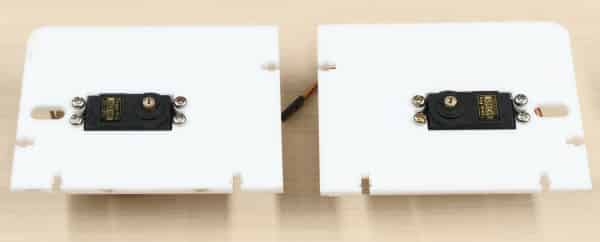
- Once done, attach that body side plate to the body base plate using M3 bolts of 12mm length and M3 nuts. Make sure that you fix the side plate in such a way that the servo head points outwards.
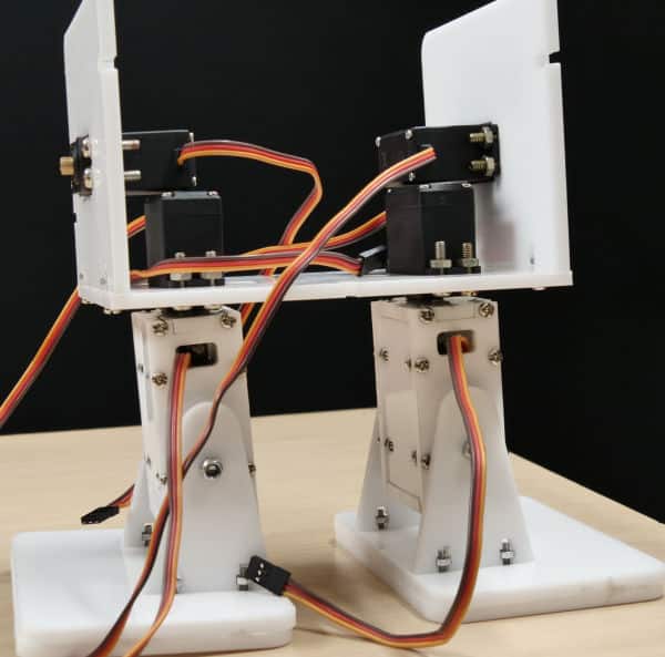
- Now, take the shoulder servo horn plate and attach the double-sided horn to it using a servo screw.
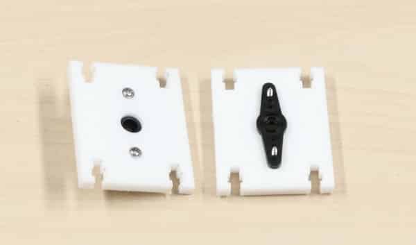
- Finally, attach the servo horn of the shoulder servo horn plate to the servo head on the body side plate using servo bolt. This allows the movement of the entire hands of the robot.
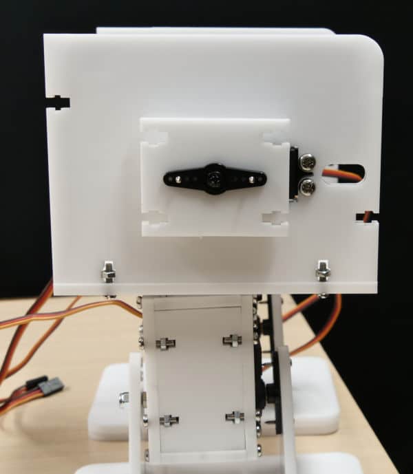
- Repeat the above steps for the other side of the robot.
5.Assembling the Hands
Let’s begin the assembly of the arm.
- Firstly, take the arm back servo plate and attach the servo horn to it using M4 nuts and bolts.
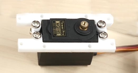
- Then, attach the arm bottom plate to the arm back servo plate using M3 bolts of 12mm length and M3 Nuts.
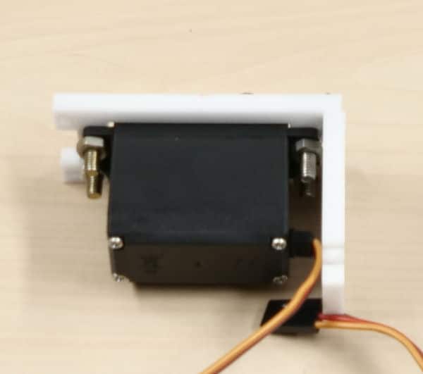
- Screw the M4 bolt and M4 lock nut into the hole given in the middle of the arm’s bottom plate.
- Next, attach the arm front plate to the arm bottom plate using M3 bolts of length 12mm and M3 nuts.
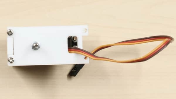
- Then, screw the claw on the arm top plate using M3 bolts of 12mm length and M3 nuts.
- Fix the arm top plate to the arm back servo and arm front plate using M3 bolts of 12mm and M3 nuts.
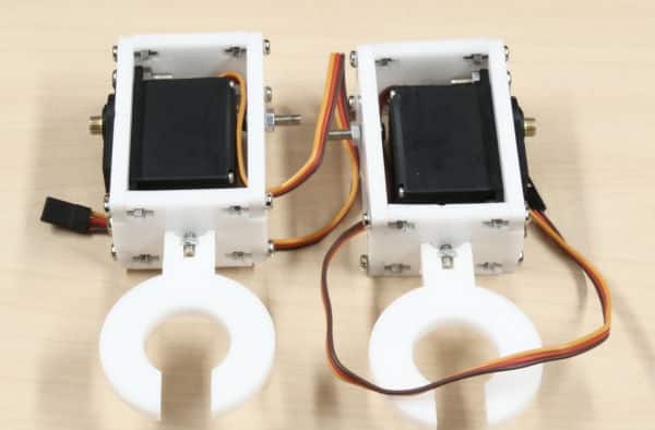
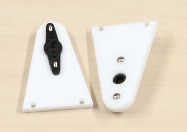
- Next, take the shoulder back plate and attach the servo horn to it using a servo screw.
- Attach the servo horn fixed on the shoulder back plate to the shoulder servo horn plate by using 12 mm M3 nuts and bolts.
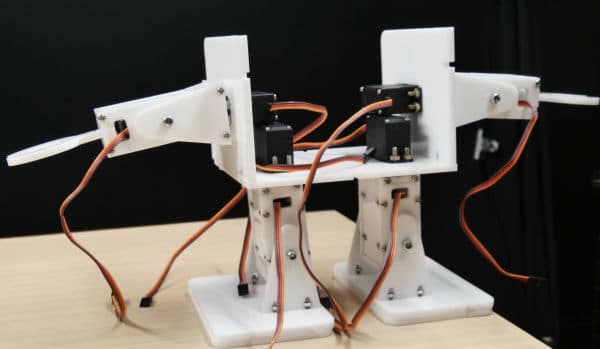
- Once the arm assemblies of both sides are completed, fix them on the body side plate by fixing the servo horn on the shoulder servo horn plate to the servo head.
- Attach the shoulder front plate to the arm back servo plate using M4 bolts and M4 lock nuts, and to the shoulder servo horn plate using M3 nuts and bolts of 12 mm length.
6.Giving the Face to the Robot
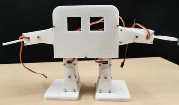
Now that the arm is attached, let’s attach the face to our bipedal robot.
Attach the body front plate to the body base plate and the side plates using M3 bolts of 12 mm and M3 bolts.
7. Assembling the Back
Finally, attach the body back plate to the body base plate and the side plates using M3 bolts of 12mm and M3 bolts.
8.Giving Vision to the Robot
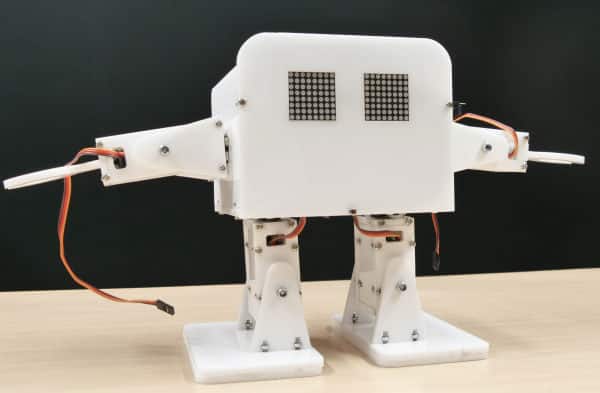
We will be using two 8 * 8 LED dot matrices as the eyes of our robot. It will express different emotions through its eyes. Let’s connect both the LED matrices to evive as given below:
- Left Dot Matrix:
- CS: 10 of evive
- CLK: 11 of evive
- DIN: 12 of evive
- VCC: 5V of evive
- GND: GND of evive
- Right Dot Matrix:
- CS: 22 of evive
- CLK: 23 of evive
- DIN: 24 of evive
- VCC: 5V of evive
- GND: GND of evive
Once connections are done, fix the matrices into the hole given on the front plate of the body.
Step-by-Step wire connection:-
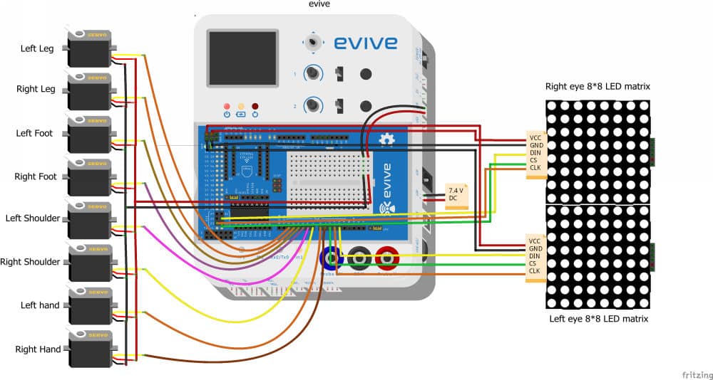
Make the connections as given below:
- Left leg servo:
- VCC (Red wire): 5V of evive
- GND (Brown wire): GND of evive
- Signal (Orange wire): Digital pin 2 of evive
- Right leg servo:
- VCC (Red wire): 5V of evive
- GND (Brown wire): GND of evive
- Signal (Orange wire): Digital pin 3 of evive
- Left foot servo:
- VCC (Red wire): 5V of evive
- GND (Brown wire): GND of evive
- Signal (Orange wire): Digital pin 4 of evive
- Right foot servo:
- VCC (Red wire): 5V of evive
- GND (Brown wire): GND of evive
- Signal (Orange wire): Digital pin 5 of evive
- Left shoulder servo:
- VCC (Red wire): 5V of evive
- GND (Brown wire): GND of evive
- Signal (Orange wire): Digital pin 6 of evive
- Right shoulder servo:
- VCC (Red wire): 5V of evive
- GND (Brown wire): GND of evive
- Signal (Orange wire): Digital pin 7 of evive
- Left-arm servo:
- VCC (Red wire): 5V of evive
- GND (Brown wire): GND of evive
- Signal (Orange wire): Digital pin 8 of evive
- Right-arm servo:
- VCC (Red wire): 5V of evive
- GND (Brown wire): GND of evive
- Signal (Orange wire): Digital pin 9 of evive
Step-by-Step Block Coding Guide:-
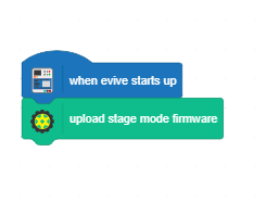
- Before we start working with the bipedal, the first thing we need to do is upload the firmware. Upload the following code to upload the firmware:
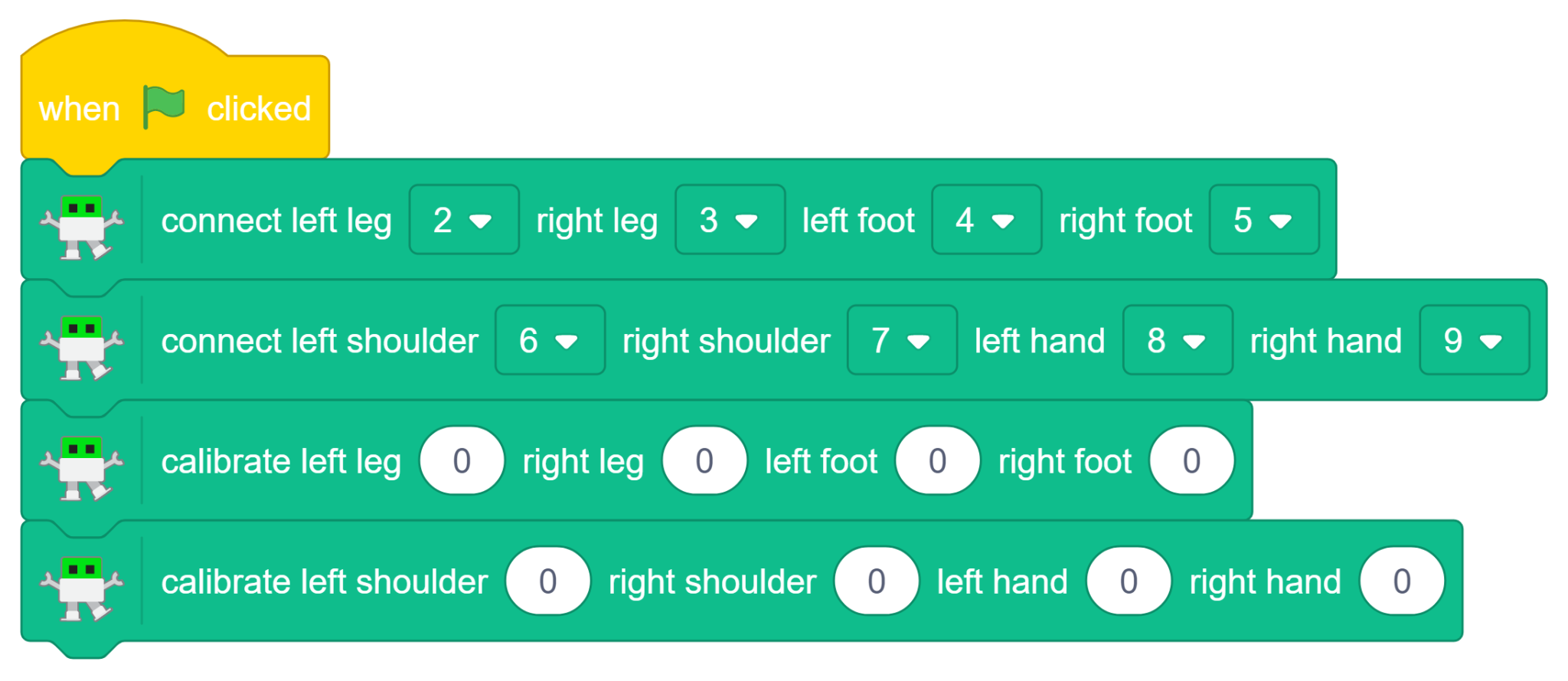
- Using the “connect left leg () right leg () left foot () right foot ()”and “connect left shoulder () right shoulder () left hand () right ()” blocks, we will first define the PWM pins off all the servos:

- To calibrate the Legs and Shoulders Servos use ‘‘calibrate left leg () right leg () left foot () right foot ()” for legs and “calibrate left shoulder () right shoulder () left hand () right hand ()” for hand block. Enter the error angles in the spaces given.
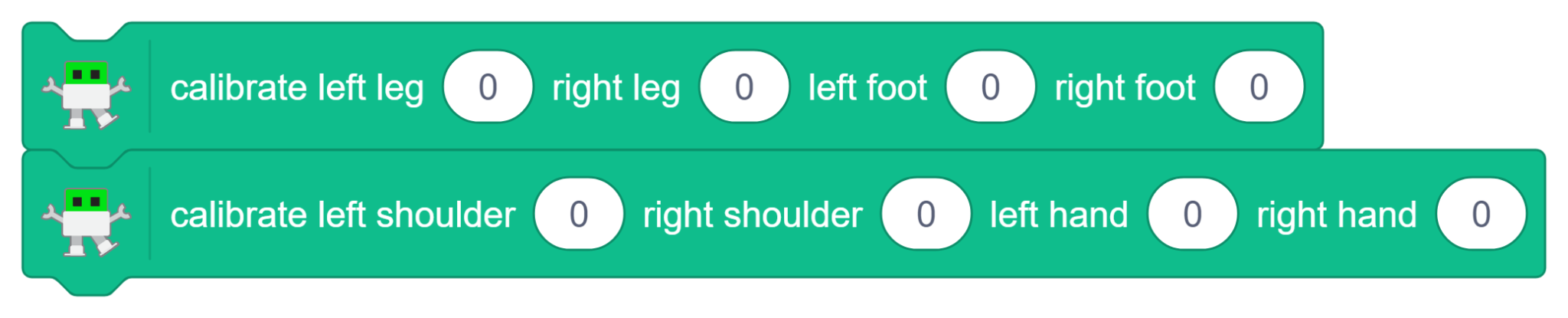
- Write the script given below to calibrate your robot:
-
This block-based script initializes a robot by connecting its legs, feet, shoulders, and hands to specific hardware ports.
-
It then calibrates all of these connected joints to a starting zero position to ensure proper alignment before any movement begins.
-
Following the connection setup, the script calibrates all of the robot’s legs, shoulders, and hands to a starting zero position.
-
This ensures the robot’s motors are perfectly aligned before any further movement commands are executed.
-
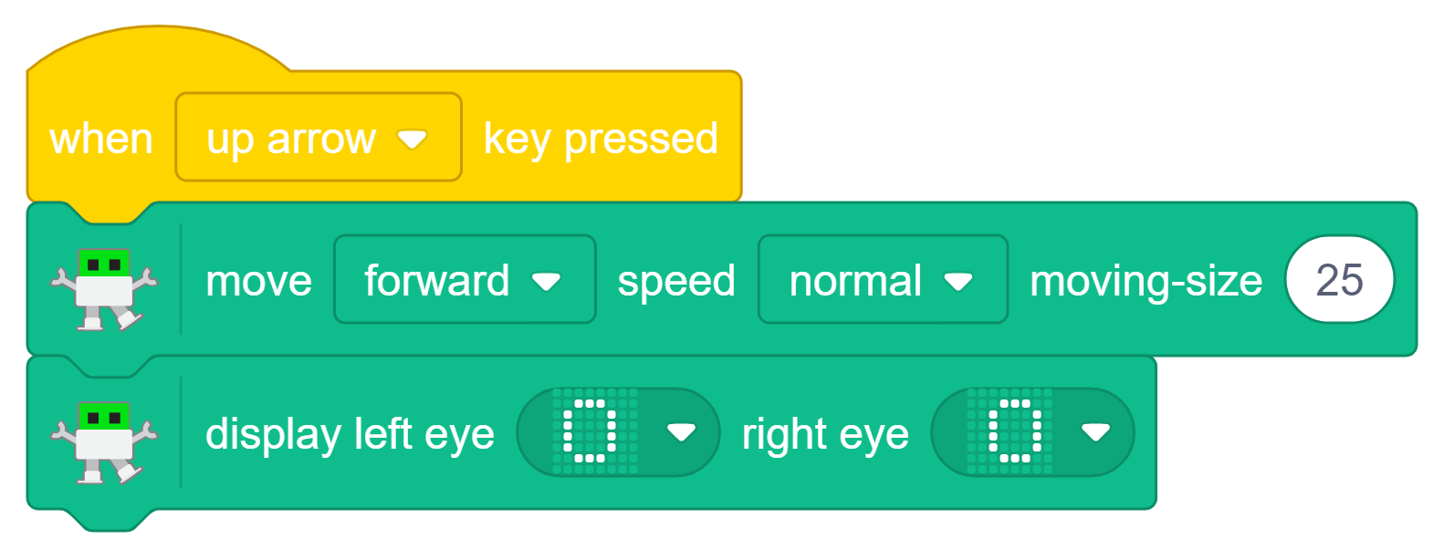
programs the robot to move forward at a normal speed whenever the up arrow key is pressed.
-
Simultaneously, it triggers the robot’s LED matrix to display a wide-eyed, circular pattern on both eyes.
-
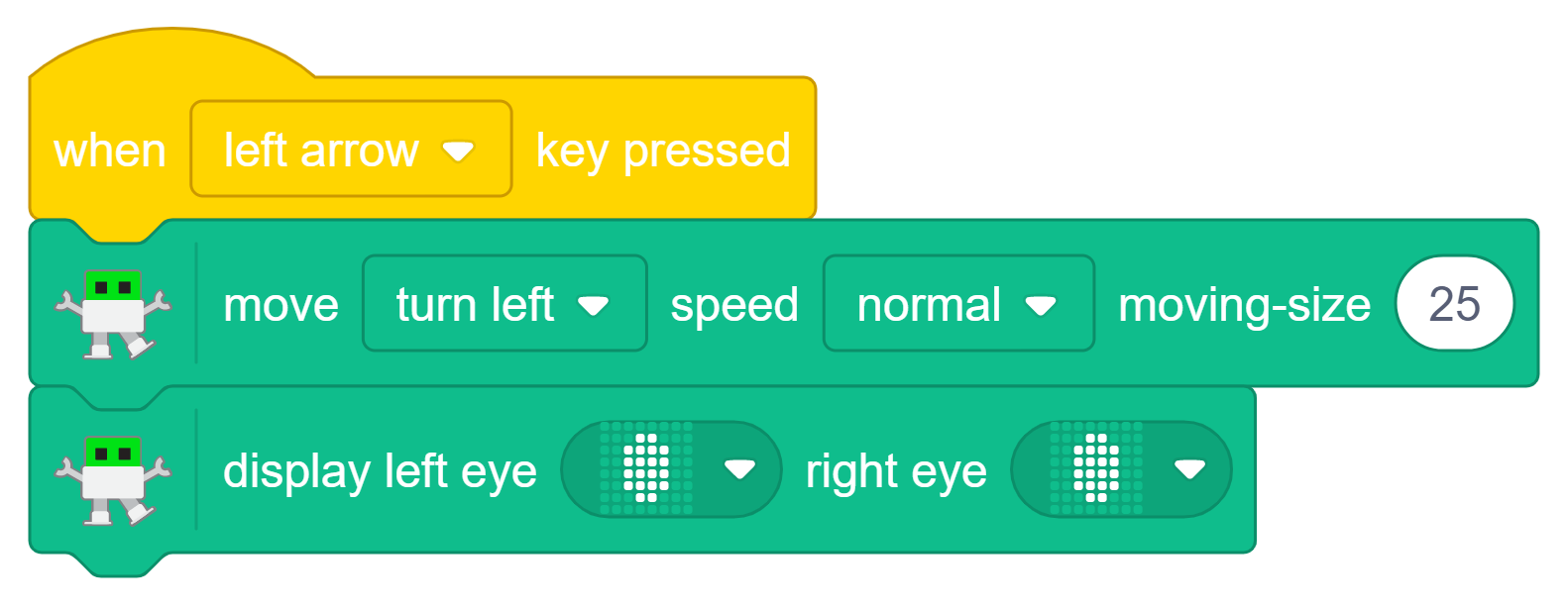
Programs the robot to turn left at a normal speed whenever the left arrow key is pressed on the keyboard.
-
Simultaneously, it triggers the robot’s LED matrix to display a specific dotted pattern on both of its eyes to match the action.
-
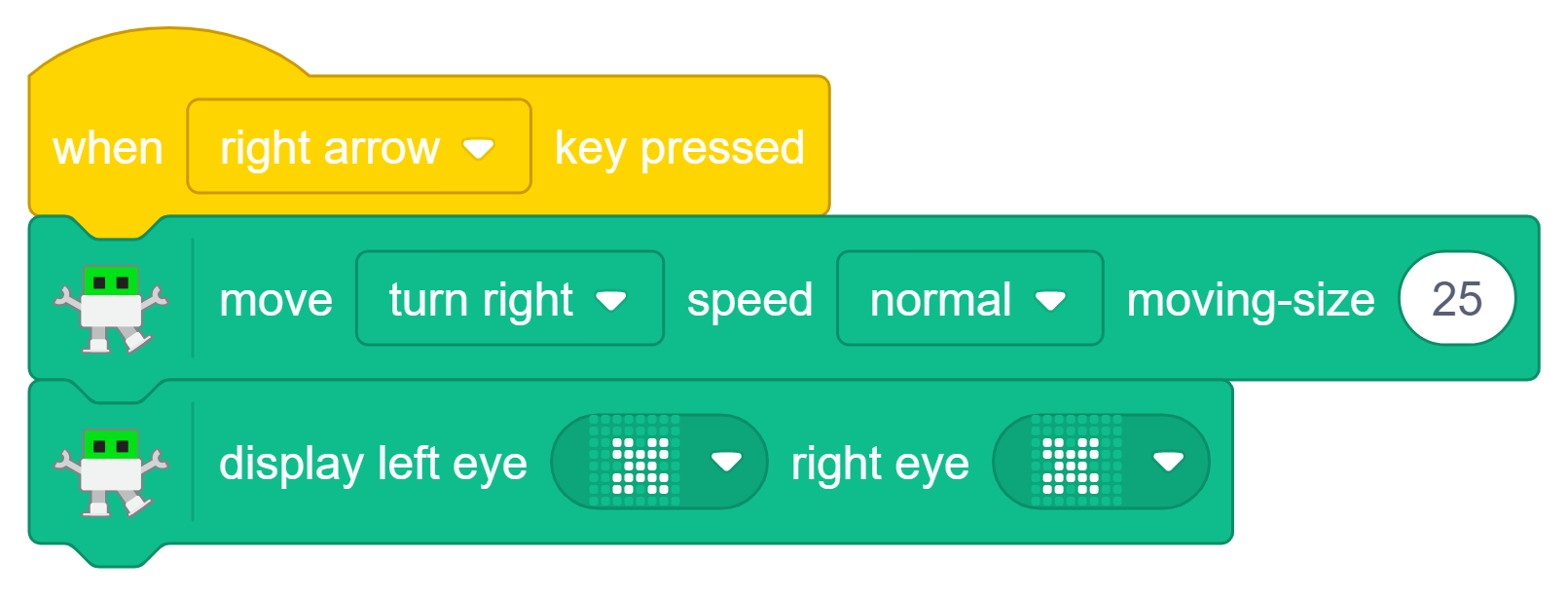
Programs the robot to turn right at a normal speed whenever the right arrow key is pressed on the keyboard.
-
Simultaneously, it triggers the robot’s LED matrix to display a specific dotted pattern on both of its eyes to match the action.
-
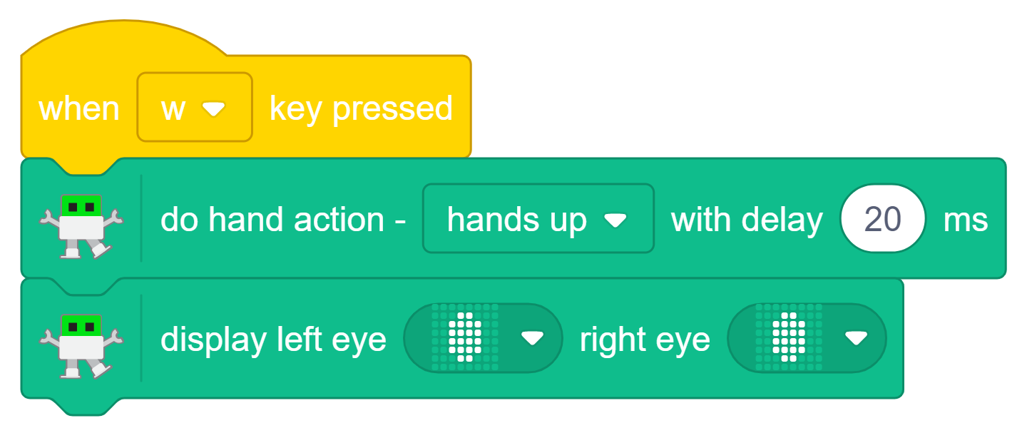
Programs the robot to hands up at a normal speed whenever the w arrow key is pressed on the keyboard.
-
Simultaneously, it triggers the robot’s LED matrix to display a specific dotted pattern on both of its eyes to match the action.
-
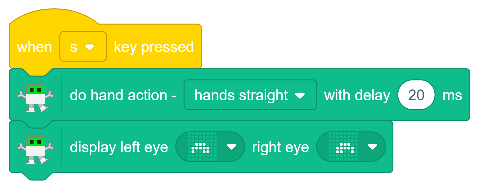
Programs the robot to hands straight at a normal speed whenever the s key is pressed on the keyboard.
-
Simultaneously, it triggers the robot’s LED matrix to display a specific dotted pattern on both of its eyes to match the action.
-
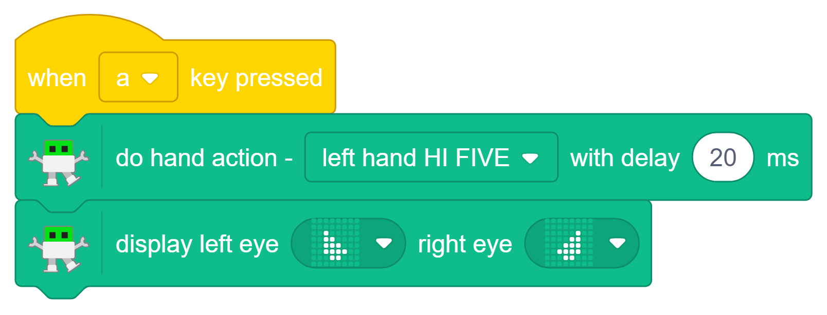
Programs the robot to left hand HI FIVE at a normal speed whenever the a key is pressed on the keyboard.
-
Simultaneously, it triggers the robot’s LED matrix to display a specific dotted pattern on both of its eyes to match the action.
-
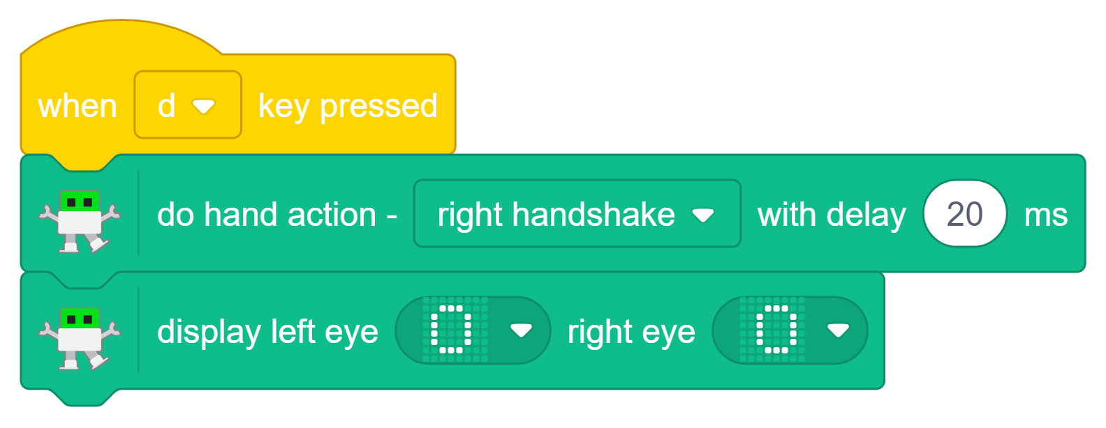
Programs the robot to right handshake at a normal speed whenever the d key is pressed on the keyboard.
-
Simultaneously, it triggers the robot’s LED matrix to display a specific dotted pattern on both of its eyes to match the action.
Conclusion:-
The project demonstrates the development of a DIY computer-controlled humanoid bipedal robot using servo motors and PictoBlox programming. It covers the robot’s assembly, calibration, and motion control, showing how coding can be used to create human-like walking movements. The project is an excellent example of integrating robotics, electronics, and programming to build an interactive humanoid robot for STEM learning and experimentation.