


The set PWM pin () output as () block controls the PWM output of a selected Arduino Uno pin from 0 to 255.
It can be used to adjust LED brightness, motor speed, and other PWM-compatible devices.

Introduction
PWM and It’s Applications
Pulse Width Modulation (PWM) is a powerful signal that allows precise control over voltage values and the time for each voltage level. By selectively choosing voltage values and durations, PWM signals can be fine-tuned to meet specific requirements. In PWM signals, the time lengths for the LOW and HIGH states of the pulse can vary, as depicted in the figure below. PWM has various applications and is commonly used to control LEDs and DC motors.
Applications
- LED Control: PWM controls the frequency of light emitted by LEDs, making them appear ON and OFF at a frequency detectable by our eyes.
- DC Motor Control: In DC motors, PWM acts as a pulse train, delivering high or low electrical power based on the width of the PWM pulses.
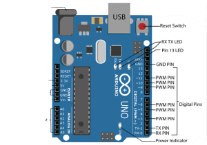
PWM pins in Arduino
Arduino boards have 14 digital input/output pins, six of which can be utilized as PWM outputs (indicated with a dash on the board). The Digital-to-Analog Converter (DAC) channel of Arduino is an 8-bit register, enabling voltage values ranging from 0 to 255 (corresponding to 0V and 5V, respectively).
Understanding Analog Output
Analog signals have variable magnitudes throughout their cycles. Examples of analog signals include the output of smoke sensors and soil moisture sensors. In Arduino, PWM pins can be used to generate analog signals as output.
Circuit Diagram
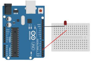
- LED+ to pin 3
- LED – to GND
Code
- Select Arduino Uno from the boards and connect it via USB.
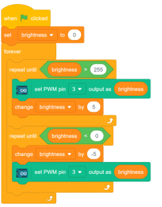
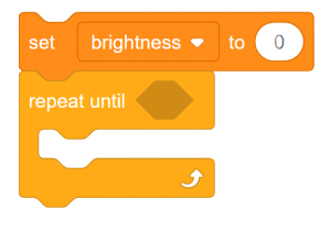
- Create a variable “brightness” and set its initial value to 0.
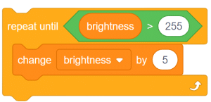
- Use the “repeat until ()” block from the Control palette.
- Check the voltage range for PWM pins (0-255) using a comparison operator.
- Increase the value of “brightness” by +5 inside the “repeat until ()” block.
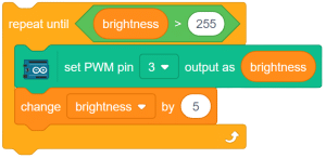
- Use the “set PWM pin() output as()” block from the Arduino palette to set pin 3 as a PWM output and adjust its voltage level using the “brightness” variable.

- Place this block inside the “repeat until ()” block.

- Set the PWM value to brightness and change the brightness by +5.
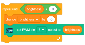
- Again add a repeat until () block and check if the brightness is greater the 0
- Now change the brightness by -5 and add give this value to PWM pin 3
- Merge all the code blocks and insert them inside the “forever” block. Also, add the “when flag clicked” event.
Script: