This example demonstrates how to set up the flame sensor with Quarky to detect heat or flame nearby. Later, we create an alarm system triggered with the flame sensor.
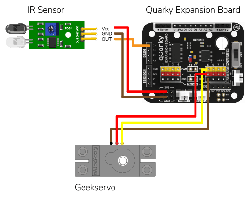
Flame Sensor Connection to Quarky
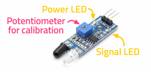
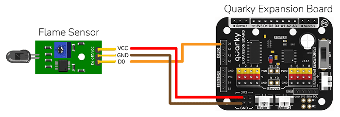
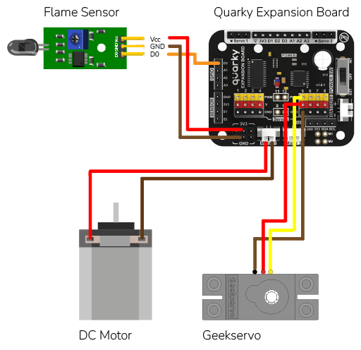
Flame sensors have 4 pins: GND, VCC, DO, and AO. You have to connect the following 3 pins to the Quarky Expansion Board:
- GND to Ground Pin of Quarky Expansion Board
- VCC to 3.3V or VCC Pin of Quarky Expansion Board
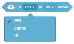
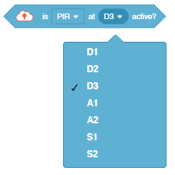
- DO to the D3 (Digital Pin) of the Quarky Expansion Board
Calibrating Flame Sensor
The sensor also has 2 LEDs – Power and Detection. The desired calibration is achieved when the sensor is inactive when there is no heat or flame nearby and active when the flame is nearby. It is visible on the detection LED.
To calibrate the flame sensor:
- Turn the power on for the sensor.
- Place the sensor close to the heat or flame. You should see the detection LED turn on.
- If the LED is Off, adjust the potentiometer until the detection LED turns on.
- Move the sensor away from the heat or flame. The detection LED should turn off.
- If the detection LED does not turn off, continue to adjust the potentiometer until it does.
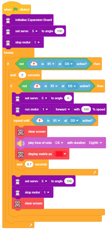
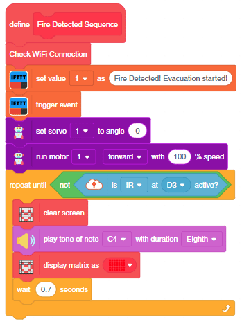
Project: Flame-based Alarm System
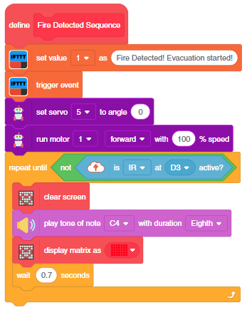
In the project, when heat or flame is detected, the alarm system starts with
- The fan turned ON.
- Quakry beeping with lights.
- The door is open for urgent evacuation.
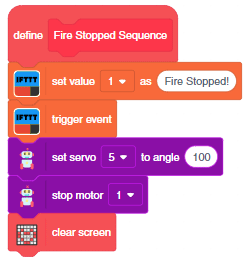
The alarm system will be on until the flame sensor stops detecting the fire.
Circuit
Connect the following modules to the Quarky Expansion Board:
- Flame Sensor
- GND to Ground Pin of Quarky Expansion Board
- VCC to 3.3V or VCC Pin of Quarky Expansion Board
- DO to the D3 (Digital Pin) of the Quarky Expansion Board
- Motor Fan: Connect the motor to the Motor Port 1 of the Quarky Expansion Board.
- Door Servo Motor: Connect the servo motor to the servo port 5 of the Quarky Expansion Board.
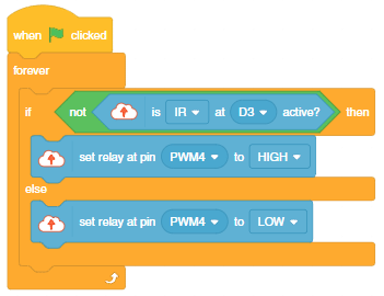
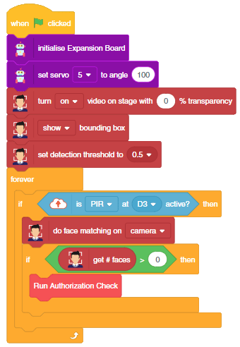
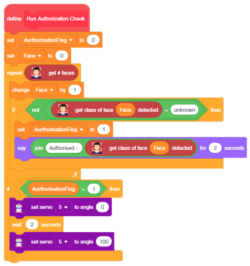
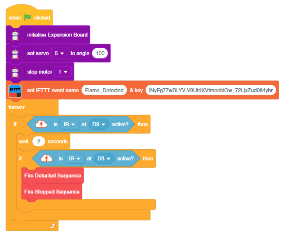
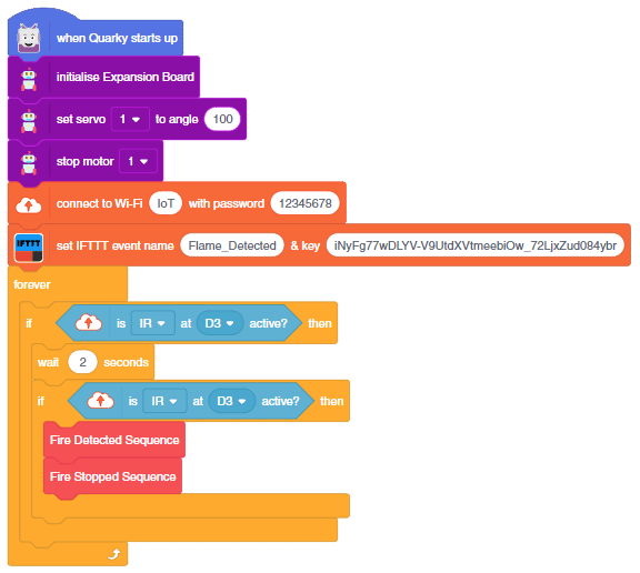
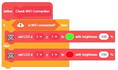
Code
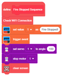
Adding IoT in Fire Alarm System
As an advanced system, we can also send the fire detection alert to the users using IFTTT. For that, we will use IFTTT webhooks.
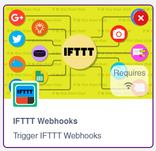
The following IFTTT sequence is to be created:
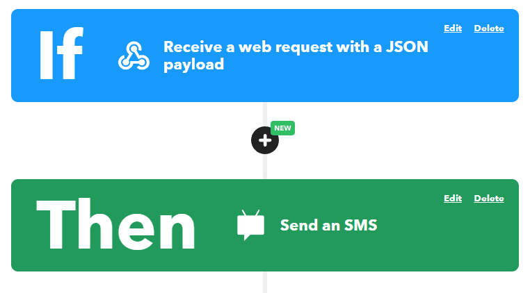
You can learn in detail how to create an IFTTT applet here: https://ai.thestempedia.com/extension/ifttt-webhooks/
Code
You can download the code from here: Flame-Based Alarm System – Stage Mode
IoT-based Fire Alarm in Upload Mode
You can also make the automatic lighting work independently of PictoBlox using the Upload Mode. For that switch to upload mode and replace the when green flag clicked block with when Quarky starts up the block.
You can download the code from here: Flame-Based Alarm System – Upload Mode