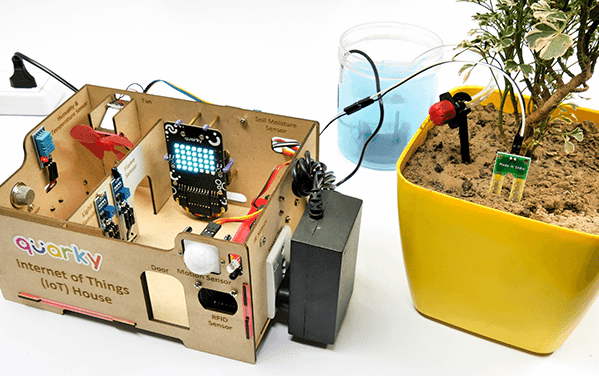
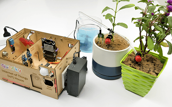
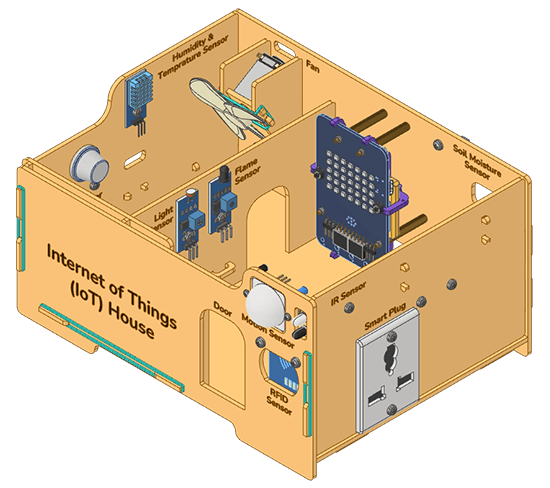
Get started exploring the potential of the Internet of Things with an easy-to-use IoT House kit designed just for beginners. Experience the wonders of the IoT firsthand!
Component Assembly Steps
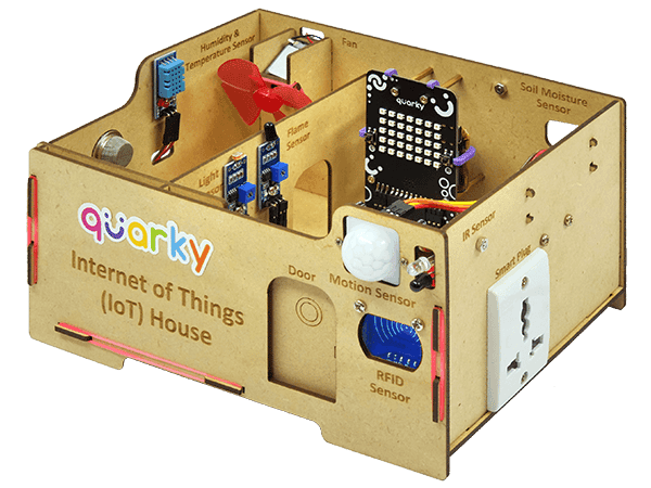
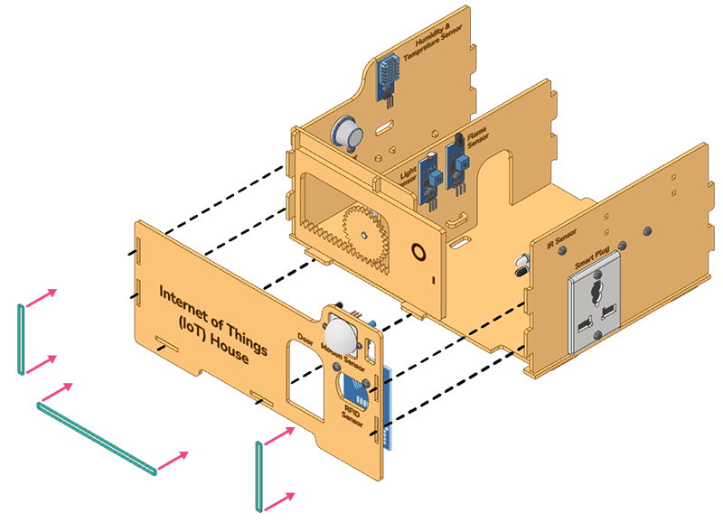
We’ll start by putting together the parts for the IoT House, each on its own MDF wall.
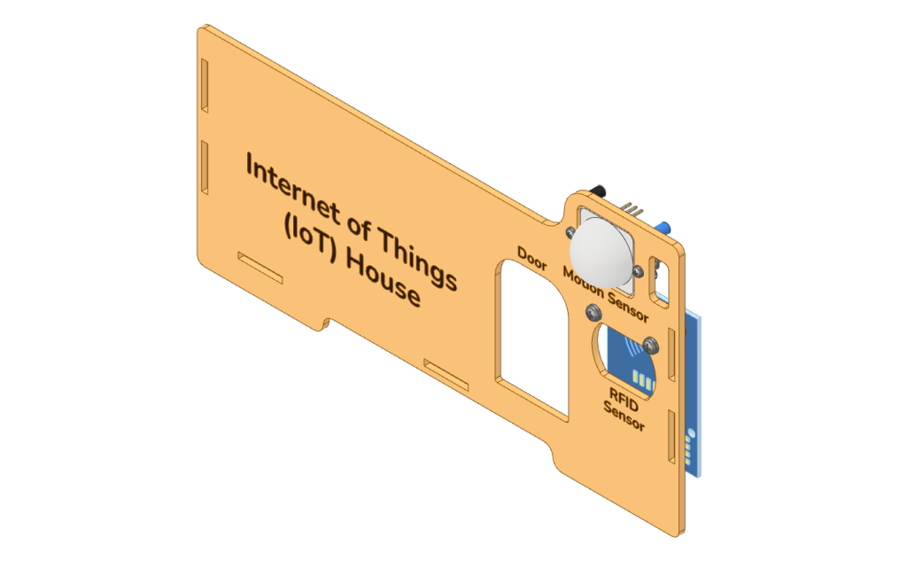
Front Wall
- Fix the Motion Sensor on the Front Wall to the back side using M2 Bolts (12mm) and M2 Nuts.
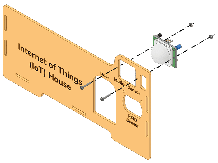
- Attach M3 Metal Standoff (10mm) at the bottom of the RFID Sensor on its front side using M3 Nuts.
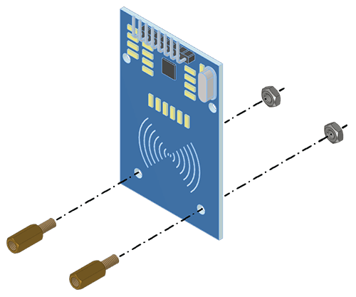
- Fix the assembled RFID Sensor to the Front Wall at the back side using M3 Bolts (8mm).
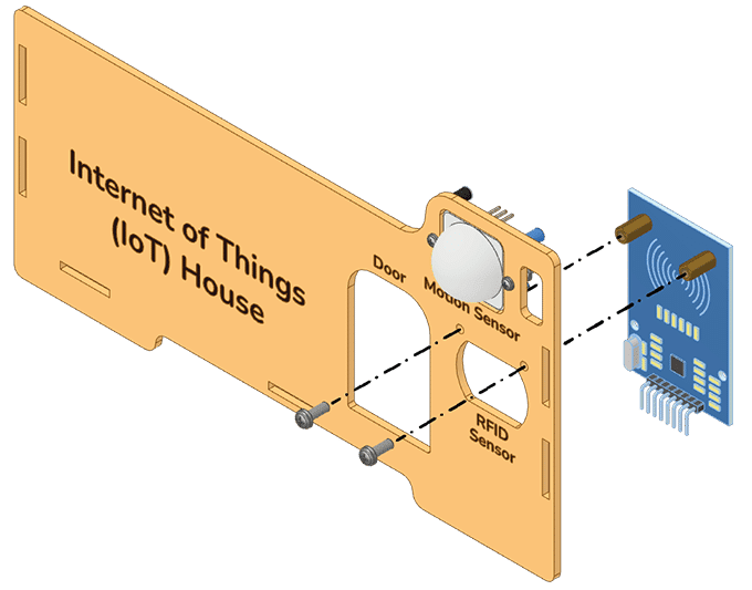
- Attach Wires to the RFID Sensor and Motion Sensor as per the Wiring Diagram.
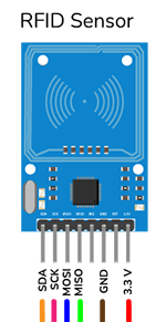
- RFID Sensor: Connect 6 Female to Male Jumpers on one end of the sensor.
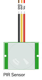
- Motion Sensor: Connect 3 Female to Male Jumpers on one end of the motion sensor.
- RFID Sensor: Connect 6 Female to Male Jumpers on one end of the sensor.

Alert: Keep the other end of the jumper wire open/unconnected. We will use them in the relevant projects.
Assembled Front Wall:
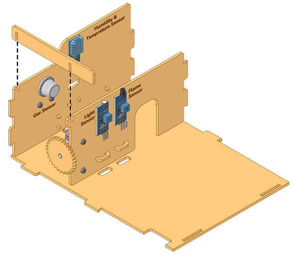
Left Wall
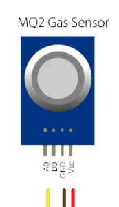
- Secure the Gas Sensor to the back side of the Left Wall with M3 Bolts (8mm) and M3 Nuts.
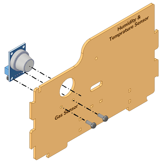
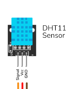
- Connect the Humidity and Temperature Sensor to the front side of the Left Wall with M3 Bolts (8mm) and M3 Nuts.
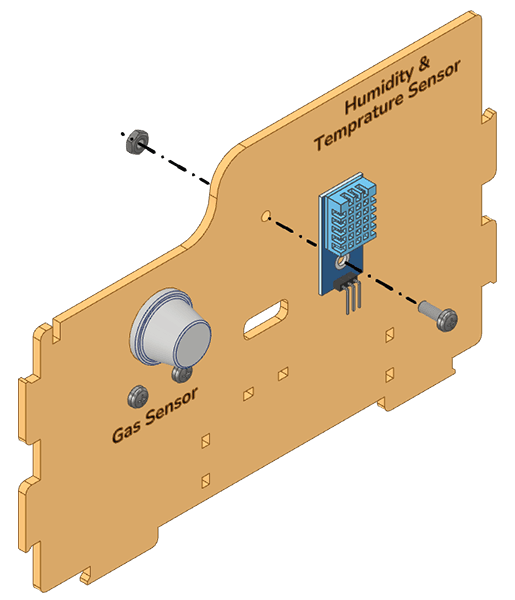
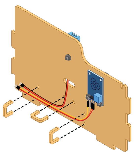
- Connect one end of the three Female to Male Jumper Cables from the Humidity and Temperature Sensor and run it through the wiring hole in the Left Wall.
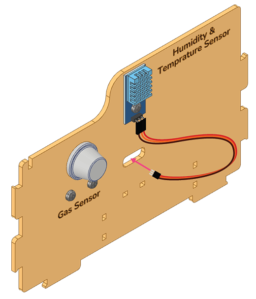
- Connect one end of the three Female to Male Jumper Cables to the Gas Sensor, then secure all the wires in place with Clips.
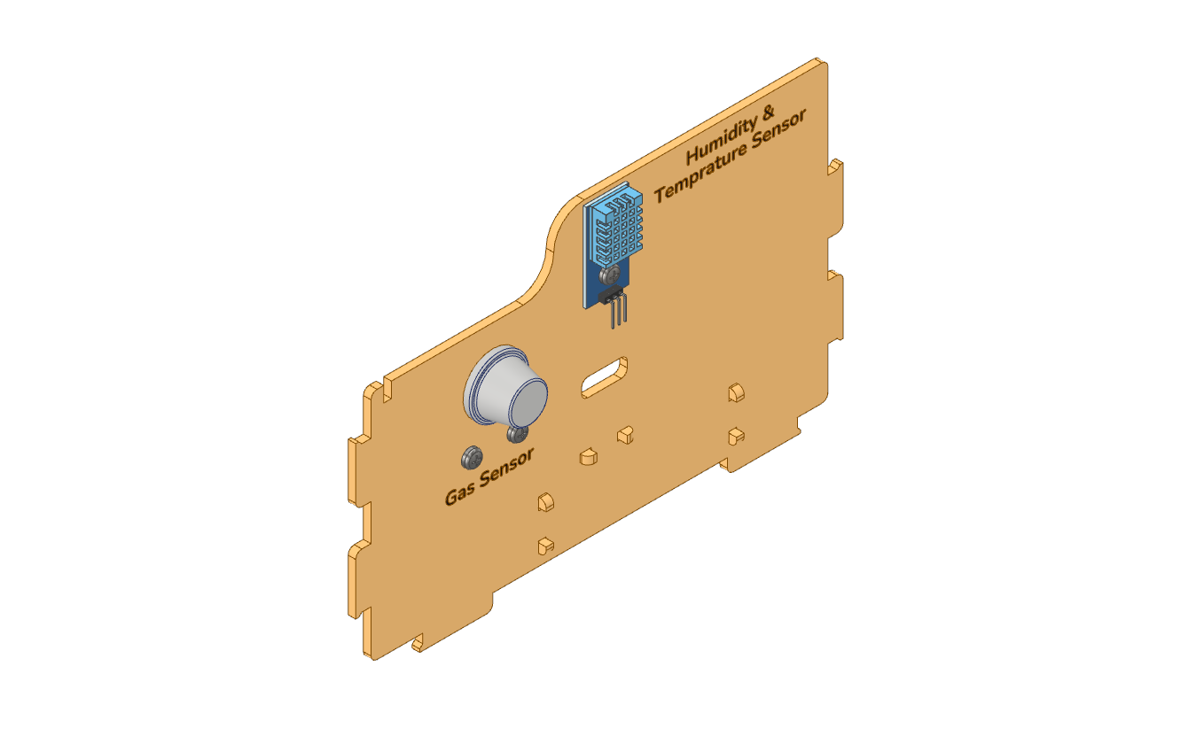
Assembled Left Wall:
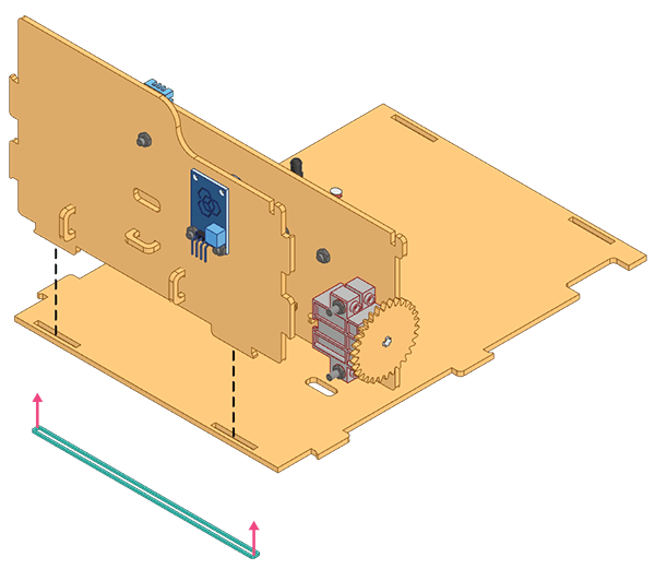
Middle Wall
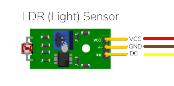
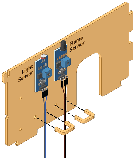
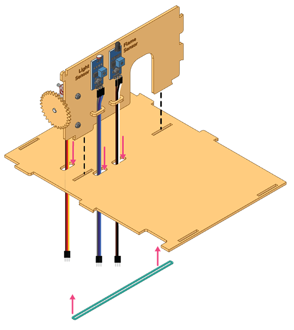
- Secure the LDR Sensor to the front of the Middle Wall using an M3 Bolt (8mm) and M3 Nut.
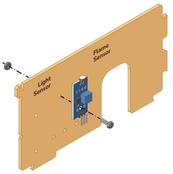
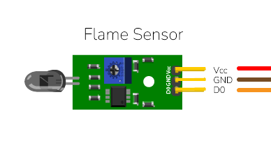
- Attach the Flame Sensor to the front side of the wall in the same manner.
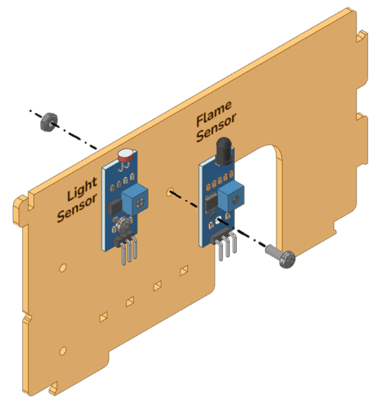
- Connect the wires to each sensor with Female to Male Jumper Cables and fasten them with Clips.
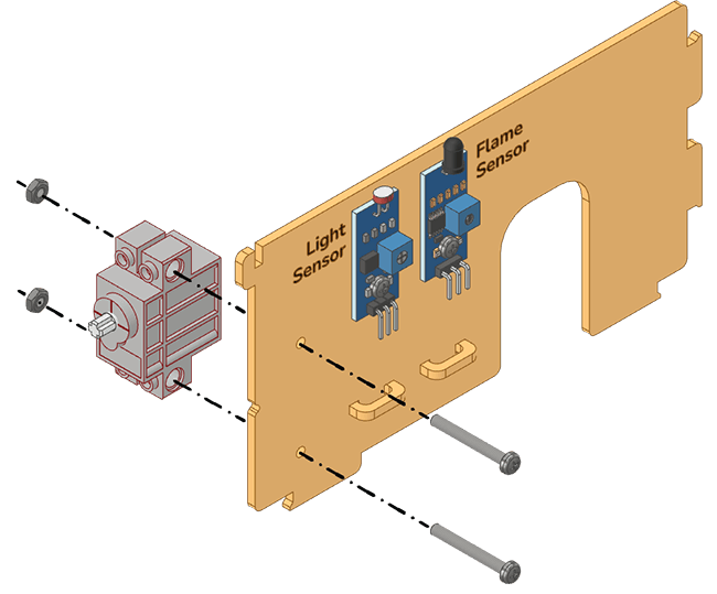
- Mount the Servo Motor at the back of the Middle Wall using M3 Bolts (20mm) and M3 Nuts.
- Place the Gear on the shaft of the Servo Motor.
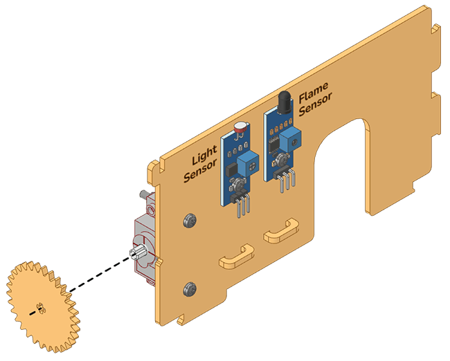
- Open PictoBlox and set the Servo Motor angle to 0 degrees. The servo head should get aligned properly.

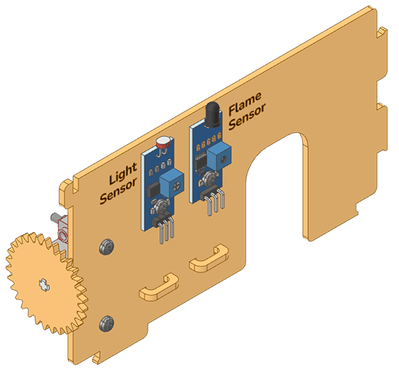
Assembled Middle Wall:
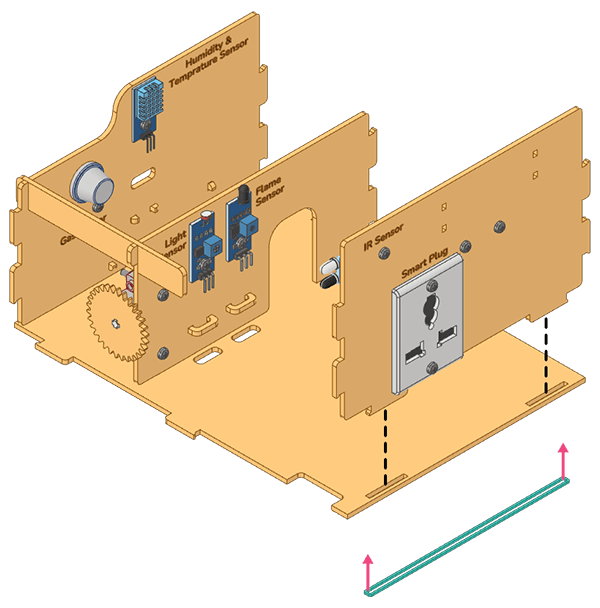
Right Wall
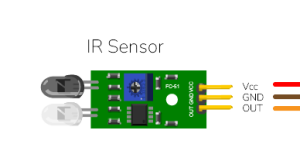
- Secure the IR Sensor to the back of the Right Wall with an M3 Bolt (8mm) and M3 Nut.
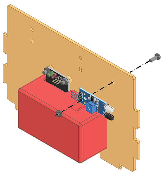
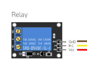
- Connect the Female to Male Jumper Cables to the IR Sensor and Relay.
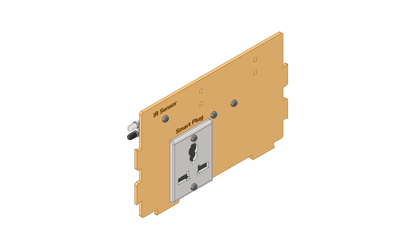
Assembled Right Wall:
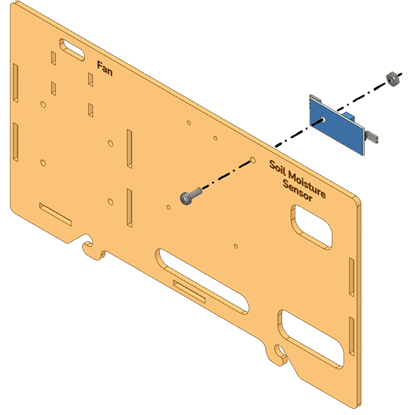
Back Wall
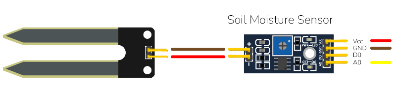
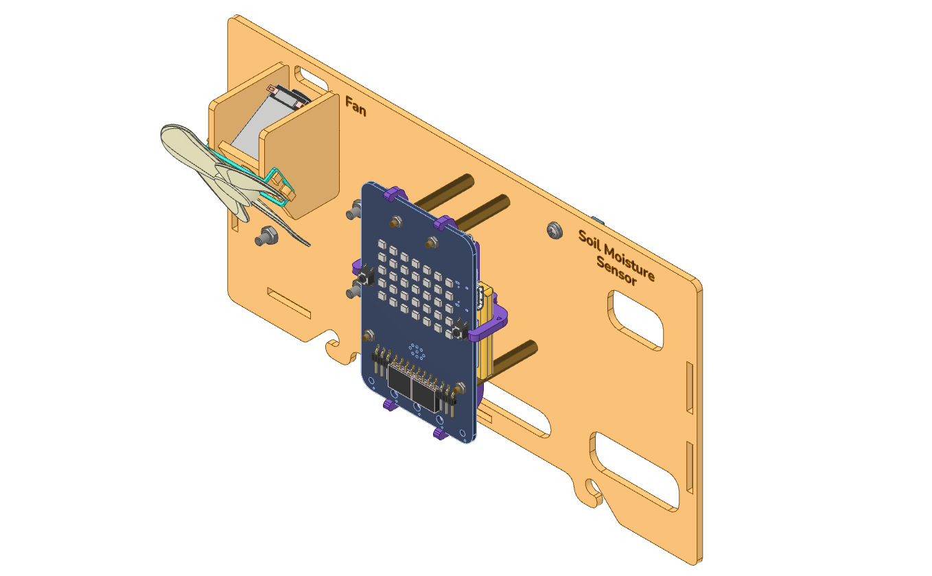
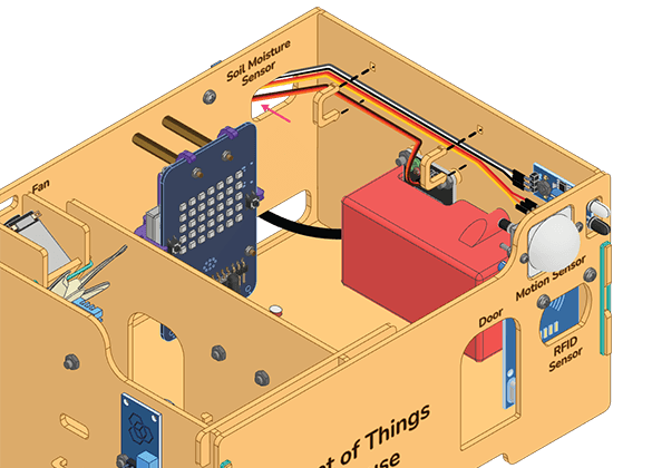
- Secure the Soil Moisture Sensor to the back of the Back Wall using an M3 Bolt (8mm) and an M3 Nut.
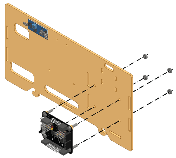
- Insert M3 Bolts (12mm) through the Expansion Board, and then slide M3 MDF Small Spacers through them.
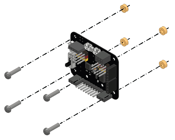
- Attach the Expansion Board to the back of the Back Wall with M3 Nuts.
- Place the Fan Mount Front into the Fan Mount Sides and secure them with a Rubber band.
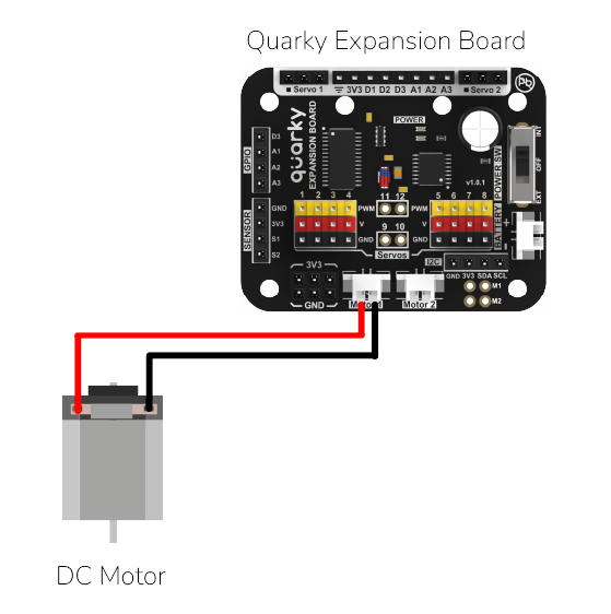
- Insert the DC Motor’s shaft into the Fan Mount Front and attach the Fan to the DC Motor’s shaft.
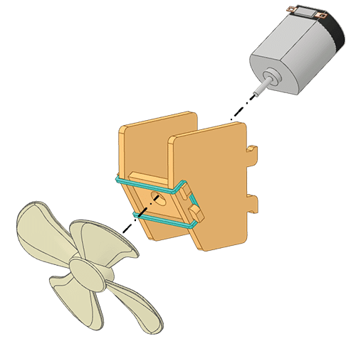
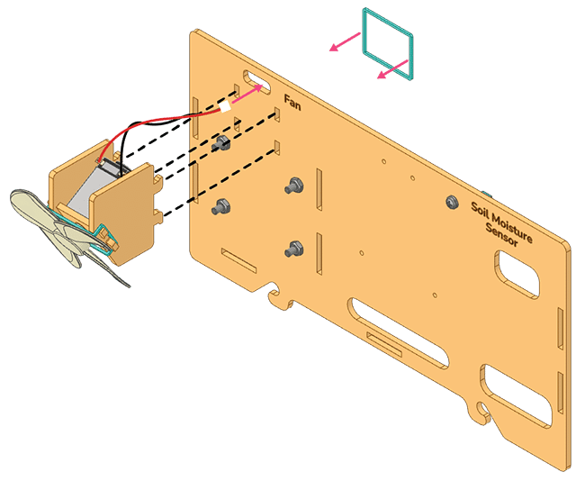
- Feed the DC Motor wire through the hole in the Back Wall and insert the Fan Assembly on the front side of the Back Wall, then secure it with a Rubber band.
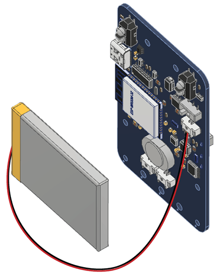
- Connect the Battery by placing it on the back of the Quarky with the red wire towards the right side.
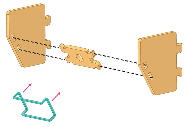
- Mount and snap the A1 Purple Parts to keep the Battery safe and secure.
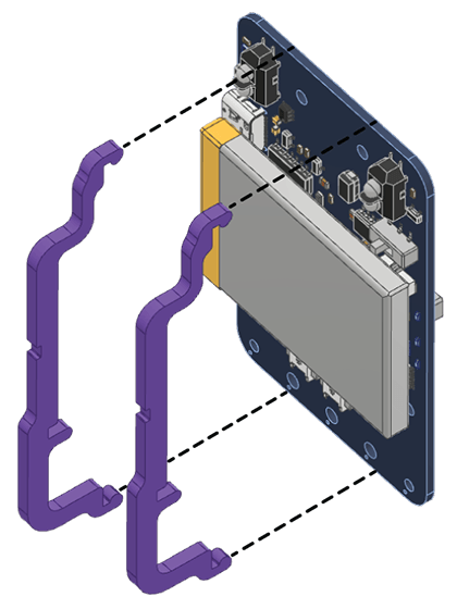
- Lock the A1 Purple Parts with an A2 Purple Part by pressing them together gently.
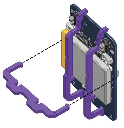
- Fix the M2 Metal Standoffs (30mm) on the back of the Quarky and fix them with M2 Nuts.
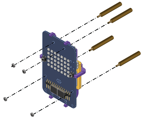
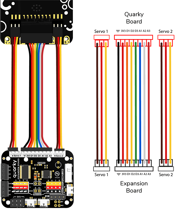
- Attach the Expansion Connectors on the Quarky according to the Wiring diagram.
- Insert the Expansion Connectors through the hole on the Back Wall from the front side and fix the assembled Quarky to the Back Wall with M2 Bolts (6mm).
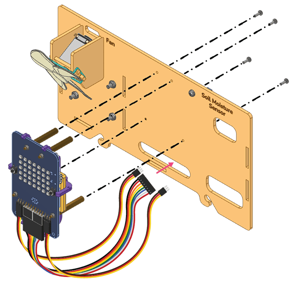
- Connect the wires to the Expansion Board. (See wiring in step no. 11)
- Attach Female to Female Jumper Cables to the Soil Moisture Sensor.
- Connect the cable DC Motor to the Expansion Board.
Assembled Back Wall:
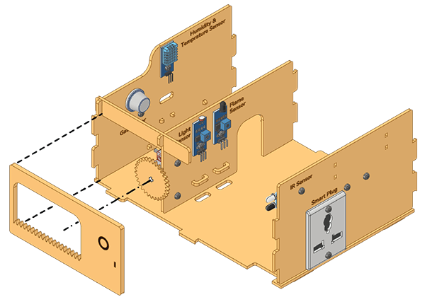
House Wall Assembly
Now we will assemble the house’s walls using Rubber bands only.
- Secure the Middle Wall to the Floor using a Rubber band.
- Attach the Left Wall to the Floor with a Rubber band.
- Connect the Door Support to the Left and Middle walls.
- Secure the Right Wall to the Floor using a Rubber band.
- Place the Door in the entrance, with the Gear on the right side of the gear rail.
- Attach the Front Wall to the Left Wall, Right Wall, and the Floor using Rubber bands.
- Attach the House’s Back Wall to the Left Wall, Middle Wall, Right Wall, and Floor using Rubber bands.
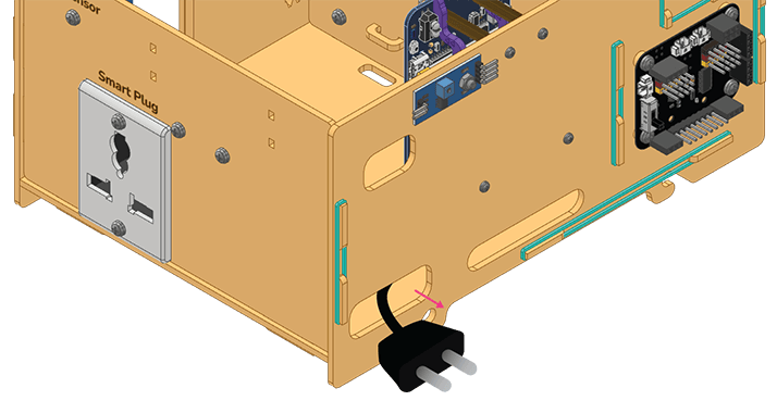
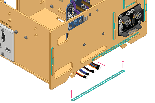
- Pass the Relay Plug through the wire hole in the Back Wall.
- Secure the wires of the Motion Sensor and IR Sensor to the right wall with Clips.
- Apply the Rubber band at the bottom of the Back Wall clipping the wires passing through the bottom.
The assembly of the IoT House is complete.
Conclusion
You can try to do the projects now:
You can also make the drip irrigation system using the following document links: