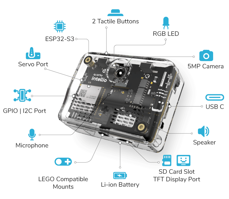
The Quarky Intellio extension allows users to control the core hardware features of Quarky Intellio directly from PictoBlox. It provides blocks and Python functions to read sensor inputs, control outputs, move servo motors, manage timing operations, perform value conversions, and enable wireless connectivity.
Using this extension, you can:
- Upload code to Quarky Intellio in Upload Mode using the when Quarky Intellio starts up block.
- Read digital input from connected sensors or devices.
- Read analog input values from pins such as A1.
- Control digital outputs by setting pins HIGH or LOW.
- Generate PWM output values for devices like LEDs or motors.
- Control servo motors by setting them to a specific angle.
- Move a servo to a specified angle over a defined duration.
- Use timer functions to measure or reset elapsed time.
- Perform mathematical conversions such as casting values or mapping ranges.
- Connect Quarky Intellio to Wi-Fi networks.
- Start Quarky Intellio as a hotspot for wireless communication.
- Retrieve the IP address of the connected device.
This extension is useful when working with core input–output operations, servo control, timing, and wireless connectivity features of Quarky Intellio.
Connecting Quarky Intellio with PictoBlox
Let’s begin by first connecting Quarky Intellio to PictoBlox. Follow the step-by-step instructions in the Quarky Intellio Connection Guide to establish the connection.
Refer to the guide here: