


Introduction
One of the most fundamental skills in robotics programming is teaching a robot to respond to human input in real time. Whether it is a Mars rover responding to a command from Earth, a warehouse robot receiving directions from a central system, or a toy car you control with your phone — at the core of every controlled robot is an input-output system: a signal goes in, and the robot acts on it.
In this project, we are going to build exactly that kind of system using PictoBlox and a Wizbot robot. Using keyboard arrow keys as our input device, we will program Wizbot to move in four directions — forward, reverse, left, and right — while simultaneously updating a visual on-screen costume to show the active direction and switching the robot’s LEDs to a corresponding colour. When no key is pressed, the robot will safely stop and the LEDs will turn off.
This project is a perfect introduction to the core principles of physical computing and robotics: how digital code translates into physical motion, how feedback systems confirm robot state, and how safe shutdown logic protects both the robot and its environment.
Setting Up Your PictoBlox Robotics Project
Step 1: Connect Wizbot to PictoBlox
- Wizbot Neo robot (fully charged).
- A computer with PictoBlox installed and Bluetooth enabled.
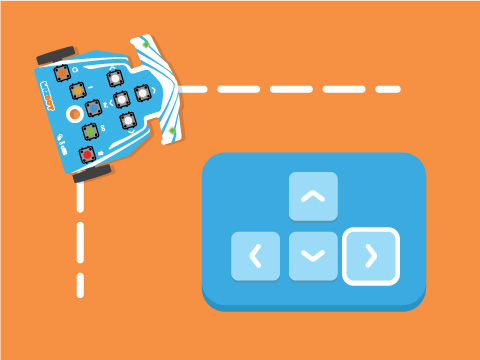
- Track Arena (line following).
Step 2: Connecting your Wizbot to Pictoblox Blocks
- Wizbot needs to be turned on; slide the 3-way power switch towards Picto coding. When you slide to PictoBlox Coding, a blue light will glow on the back side with a ‘troo-tooi’ sound.
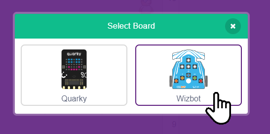
- Click on the Board tab on the top navigation bar and select Wizbot Neo.
- Now, click on connect and choose Bluetooth.
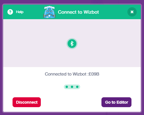
- Your Wizbot has a unique code mentioned on it. Select your Wizbot from the list and click on Connect.
- Wizbot plays a confirmation sound on connecting.
- Voila! Your wizbot is now connected to PictoBlox!
- Remove the Tobi sprite.
Step 3: Load the WizBot sprite and costumes.
Add the Wizbot sprite from the PictoBlox sprite library. This sprite comes pre-loaded with five costumes:
- Arrow1-a — right-pointing arrow (right movement)
- Arrow1-b — left-pointing arrow (left movement)
- Arrow1-c — down-pointing arrow (reverse movement)
- Arrow1-d — up-pointing arrow (forward movement)
- Wizbot — the default robot icon (stationary state)
Step-by-Step Block Coding Guide
Set Initial Sprite Position and Size
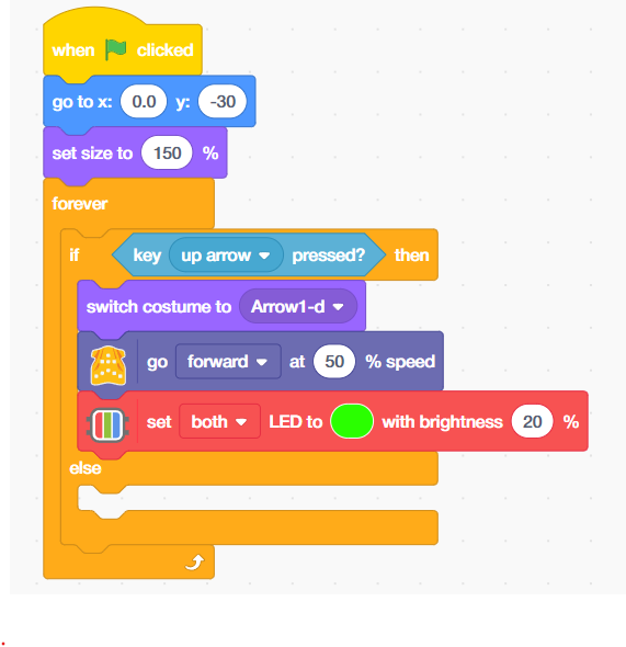
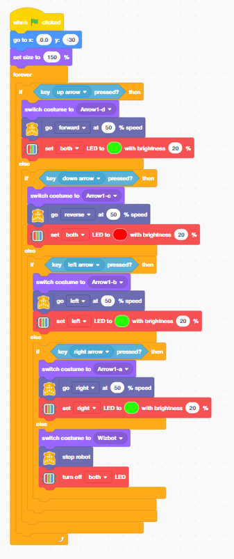
- Add the “when flag clicked” block from the event palette.
- At the start of your script, place a “go to x: [0.0] y: [-30]” block from the Motion palette and a ‘set size to [150] %’ block from the Looks palette. These position and scale the Wizbot sprite clearly at the centre bottom of the stage.
- From the Control palette, add a “forever” loop. Every block in the remainder of this script goes inside this forever loop. This loop is the heartbeat of the robot controller — it never stops checking for input as long as the project is running.
![]()
Direction 1: Up Arrow Key — Forward Movement (Green LED)
Inside the forever loop, place an if-then block. Set its condition to ‘key [up arrow] pressed?’ from the Sensing palette. When the up arrow key is held, three things happen simultaneously:
- Add the “switch costume to [Arrow1-d]” block from the Looks — the sprite shows an upward arrow, giving visual confirmation of forward direction.
- From the Wizbot palette “Go forward at [50] % speed” block, the Wizbot motor controller drives both motors forward at 50% speed. 50% provides a safe, controllable speed for indoor robotics.
- Add “set both LEDs to GREEN with brightness 20%” — both onboard LEDs light up green. Green universally signals a safe or go state in robotics and engineering.
Robotics Concept: Motor speed as a percentage corresponds to a PWM (Pulse Width Modulation) duty cycle sent to the motor driver chip. 50% PWM means the motor receives power for half of each pulse cycle — roughly half the maximum rotational speed.
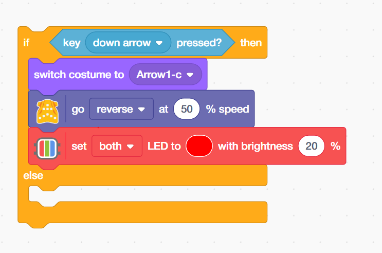
Direction 2: Down Arrow Key — Reverse Movement (Red LED)
- Add the next condition: “key [down arrow] pressed?” When the down arrow is held:
- From the Wizbot palette, add the “switch costume to [Arrow1-c]” block—the sprite displays a downward arrow confirming reverse direction.
- Add the “go reverse at [50]% speed’ block from the LEDs palette — both motors drive in reverse at 50% speed, moving the robot backward.
- Add the “set both LEDs to RED with brightness 20%” block from the LEDs palette — both LEDs light up red, signalling reverse movement. Red for reverse is a standard convention in vehicles, industrial robots, and safety systems worldwide.
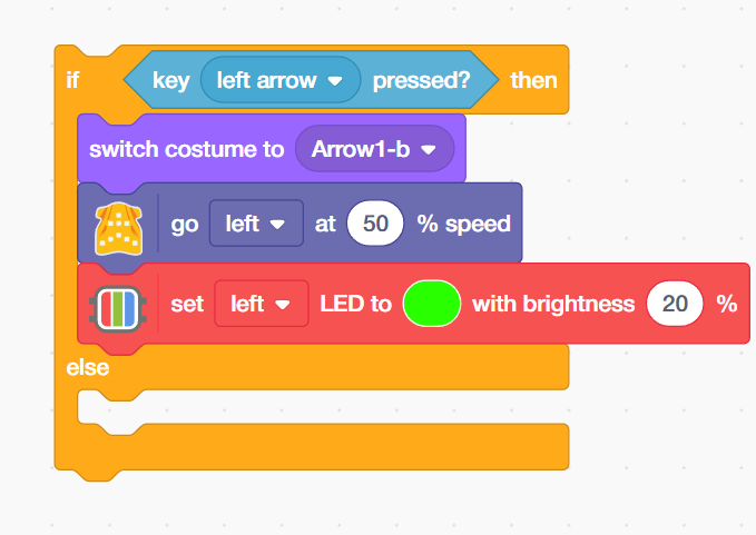
Direction 3: Left Arrow Key — Left Turn (Left LED Green)
Add the next condition: key [left arrow] pressed? When the left arrow is held:
- Add “switch costume to [Arrow1-b]” block — the sprite shows a left-pointing arrow.
- Add “go left at [50] % speed” — the motor controller executes a left turn. In a differential-drive robot, this means the left motor slows or stops while the right motor continues forward.
- Add “set left LED to GREEN with brightness 20%” — only the left LED lights up. Illuminating only the turning-side LED mirrors a vehicle’s turn indicator – an intuitive directional signal.
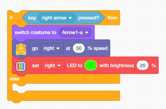
Direction 4: Right Arrow Key — Right Turn (Right LED Green)
Add the next condition: key [right arrow] pressed? When the right arrow is held:
- “switch costume to [Arrow1-a]” — the sprite shows a right-pointing arrow.
- “go right at [50] % speed” — the motor controller executes a right turn (left motor drives, right motor slows or stops).
- “set right LED to GREEN with brightness 20%” — only the right LED lights up, mirroring the direction of the turn.
The Else Branch: Safe Stop and LED Off — Critical Robot Safety Logic
The final ‘else’ branch handles the case where NO arrow key is pressed — and it is perhaps the most important part of the entire script:
- Add the “switch costume to [Wizbot]” block from the Looks palette—the sprite returns to the neutral robot icon, indicating the robot is stationary.
- From the Wizbot palette, add the “stop robot” block — the Wizbot block sends a stop command to the motor controller, cutting motor power and bringing the robot to a halt.
- Add the “turn off both LEDs” block from the LEDs palette—all onboard LEDs switch off, returning the robot to its default idle state.
Output
Conclusion
In this robotics and STEM project, we built a complete keyboard-controlled robot system in PictoBlox using the Wizbot robot. We programmed directional motor control for forward, reverse, left, and right movement; synchronised on-screen costume animations to visually confirm the active direction; implemented LED colour and side-specific feedback to communicate robot state; and added a critical fail-safe stop behaviour using a default else branch.
Along the way, we explored foundational robotics engineering concepts — real-time control loops, PWM motor speed control, differential drive locomotion, H-bridge motor drivers, and multi-output feedback system design. These are the same principles used by professional robotics engineers designing educational robots, autonomous vehicles, industrial arms, and surgical systems.
Whether you are exploring this project in a school coding lab, an Atal Tinkering Lab (ATL), a STEM innovation lab, or at home — the skills you have built here are the true building blocks of modern robotics. Every robot in the world starts with the same foundation: an input, a control loop, and an output. Now you know how to build all three.