introduction
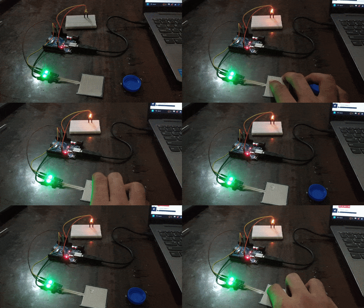
The raindrop sensor is an analog-type sensor that effectively measures changes in resistance when it encounters water. This property makes it an ideal choice for detecting rain and water presence in various applications. While typically designed with two pins, there are also versions available with a controller module, effectively converting it into a three-pin sensor for enhanced functionality.
Circuit

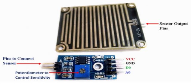
To set up the raindrop sensor circuit, make the following connections:
- Sensor:
- VCC: Connect to the 5V power supply
- GND: Connect to ground (GND)
- A0: Connect to analog input pin A0
- Buzzer:
- Buzzer+: Connect to digital pin D13
- Buzzer-: Connect to ground (GND)
Code
- Add an “if-else” block from the controls palette.

- Insert a comparison operator into the “if” block from the operators palette

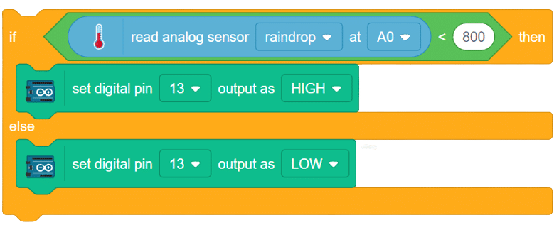
- Check whether the value of the raindrop sensor is below a certain threshold, let’s say 800. From the Arduino sensor palette, add “read analog sensor () at pin ()” and place it in the blank space of the operator. Choose “raindrop sensor” from the drop-down menu.

- If the value is below the set limit, activate the buzzer (alarm) connected to pin 13. Add set digital pin () output as () from Arduino palette within the “if” block. In the “else” part, ensure the alarm remains off when the raindrop sensor value is above the set limit.
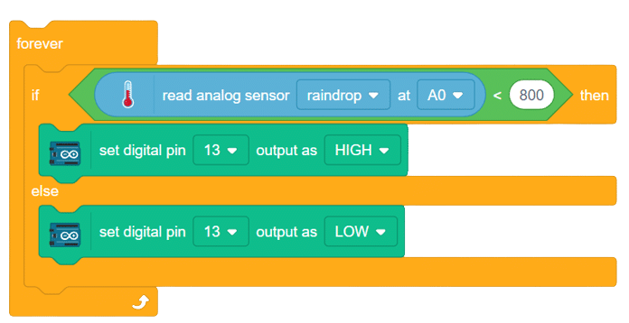
- Add the above set of code inside a “forever” block to continuously monitor the sensor’s readings.
- Finally, add a “when flag clicked” block at the start of the code to initiate the raindrop sensor monitoring.
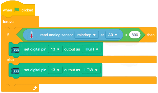
Script

Output
