Introduction
Accelerometers are vital sensors used to measure acceleration in one, two, or three axes, finding applications in robotics, gaming, and motion-sensing projects. In this example, we will guide you through connecting an MPU6050 accelerometer, a widely available 6-axis accelerometer and gyroscope module, to an Arduino board.
Our goal is to interface the accelerometer with Arduino and determine the angular movements of an object along the x-axis and y-axis.
Circuit Diagram
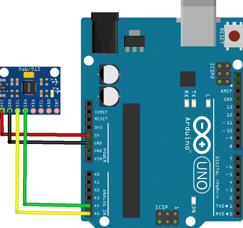
Connection
- Connect sensor VCC to 5V of the Arduino
- GBD to Arduino GND
- SCL to A5 of the Arduino.
- SDA to A4 of the Arduino.
Code
- Open PictoBlox and create a new file.
- Change the scripting mode from “stage” mode to “upload” mode.
- Click on the extension button and add the communication extension.
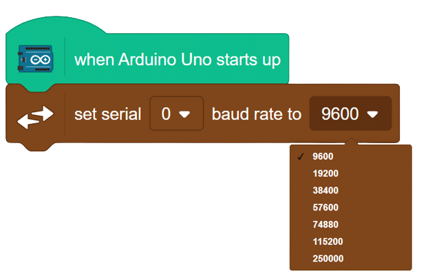
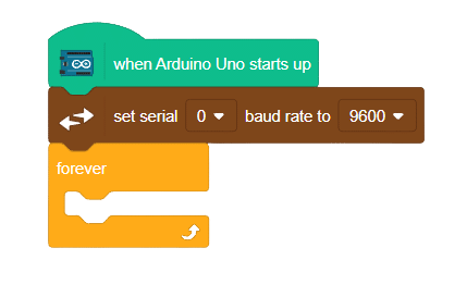
- From the Arduino palette, drag the “when Arduino starts up” block into the scripting area.

- click on communication extensions and drag “set serial () baud rate to () ” into the scripting area.
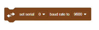
- Set the baud rate to 9600.
- From the controls palette, add the “forever” block.
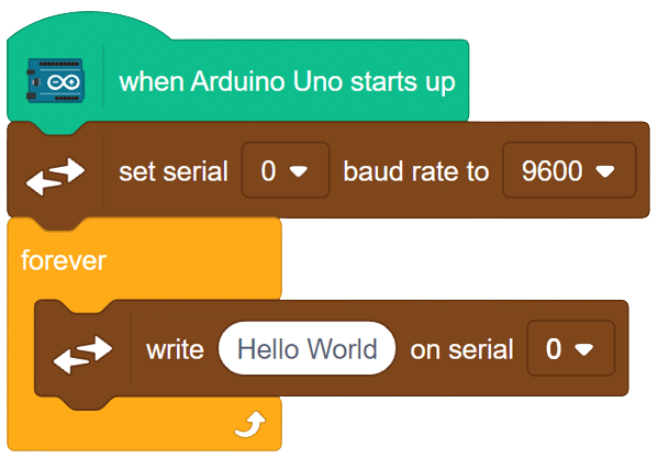
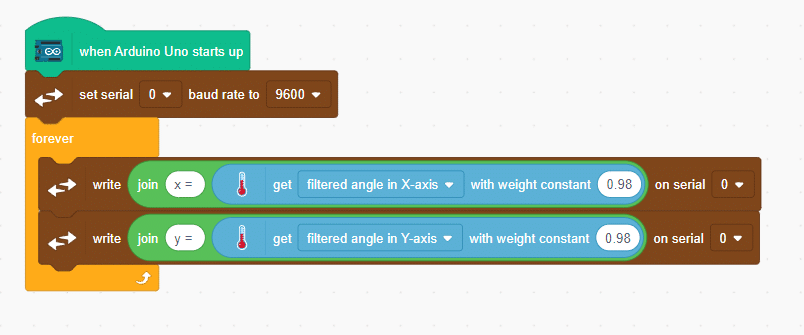
- Since the sensor is connected to Arduino, communication is enabled. Now, to write/print information on the serial monitor, go to the communication palette, drag the “write () on serial ()” block, and put it inside the forever block.
- Insert the “join” block in place of “Hello World” from the operators palette.
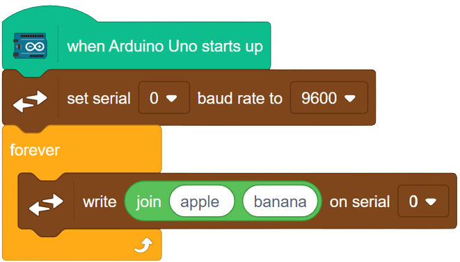
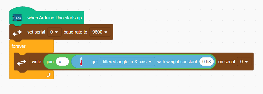
- To find the angle along the x-axis, change “Apple” with “x =” and in place of “Banana,” add the “get () with weight constant ()” block and choose “filtered angle in x-axis.”
- Repeat the above steps for the y-axis
 Add a “wait” block to read the values clearly..
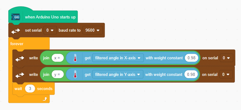
- Now, upload the code into the board and check for the output on the serial monitor.
Final Script

Output