


Introduction
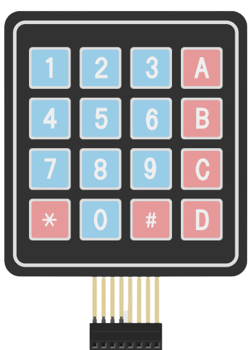
A 4×4 keypad module is an electronic input device commonly used in various applications for interfacing with microcontrollers and other digital systems. It consists of a grid of buttons arranged in a 4×4 matrix, resulting in a total of 16 buttons. Each button corresponds to a specific alphanumeric character, symbol, or command.
Working Principle: A technique called “keypad scanning” is used to read input from the keypad. The microcontroller scans the rows and columns one by one. It sets one row to HIGH and reads the column pins to detect if any button in that row is pressed. If a button is pressed, the corresponding row and column will intersect, allowing the microcontroller to determine the button that was pressed.
Applications: 4×4 keypad modules are widely used in various applications that require user input, such as security systems, door locks, industrial control panels, calculators, home automation, and more.
In this example, we will be interfacing the keypad module with Arduino and try to read the button value from the keypad module. let’s begin!!
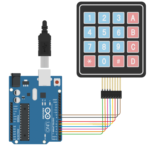
Circuit diagram
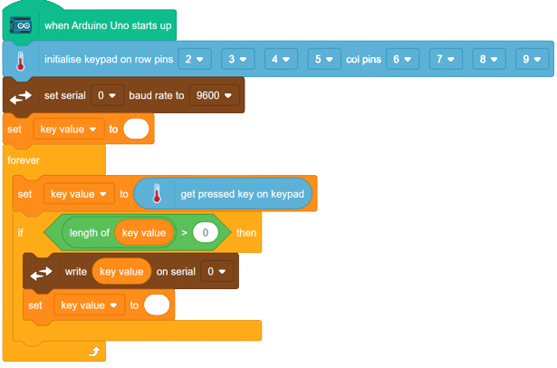
Code
- Open pictoblox and create a new file.
- from boards, select Arduino Uno.
- change Scripting mode from stage to upload.
- from extension button add “communication” extension and “Advance sensor” extension.
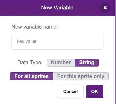
- create a variable “key value” of type string.
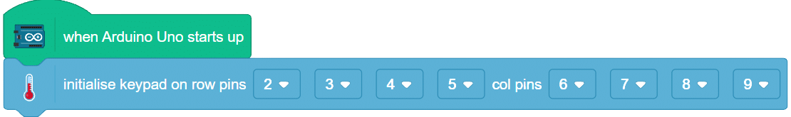
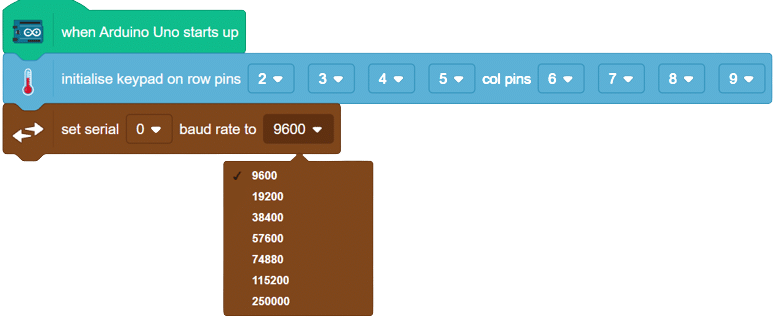
- From Arduino palette, add “When Arduino Starts up” block into the scripting area.

- From advanced sensors, Drag initilize keypad module block and add with above block.
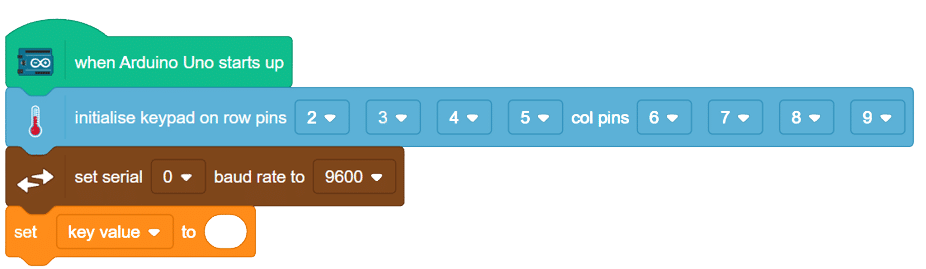
- Now we need to start the Serial communication for Arduino. From the communication palette add Now from variable palette, add “set () to ()” block with above block “Set Serial() baud rate to ()” in the script and set baud rate to 9600.
- Now from variables, we block “set () to ()” select the key value from the list and remove the 0 (make a empty string variable).
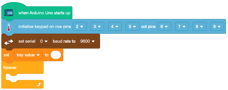
- Add a forever loop from controls palette.
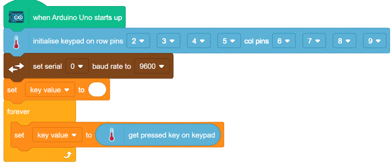
- Now from advanced sensors store the value of key pressed in key value variable.
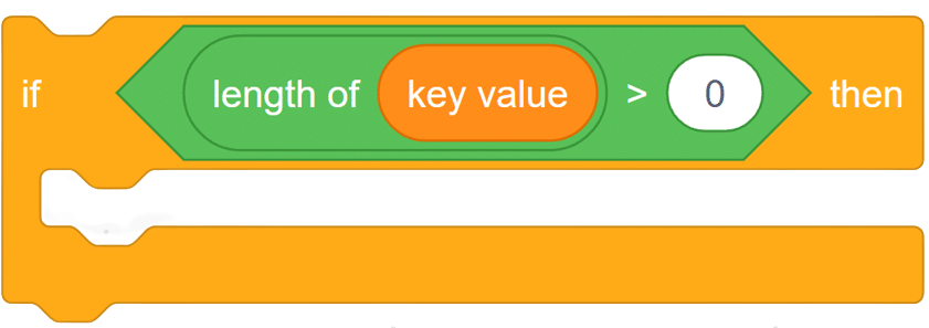
- Add a if block from controls palette into the scripting area and add greater than operator from operator palette.
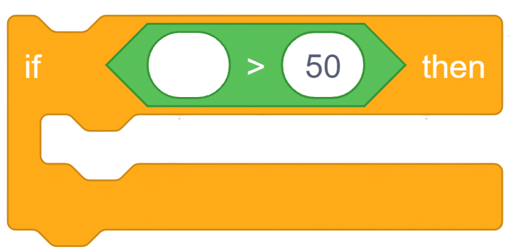
- Now if the length of key value operator is greater than 0, that means the user has pressed a key. Use lenght of ( ) block from operators
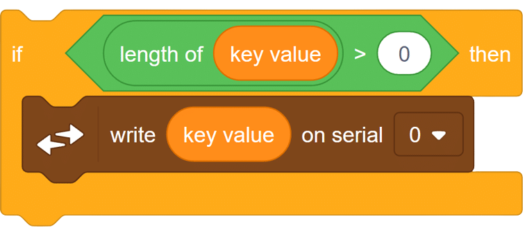
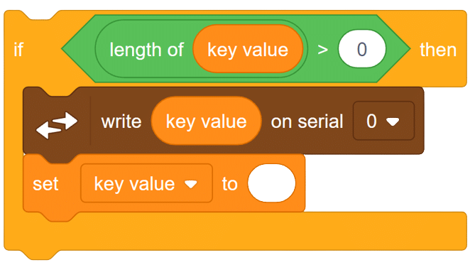
- Inside this if block we will be print the key value on Serial monitor using the communication palette. use the block “write () on Serial ()” from communication palette and place the key value variable in the space provided.
- Now delete all the data of key value variable using “set () to ()” block from variables.
- add this if block in forever block.
in this way we can connect our keypad module with Arduino.
Output:
OUTPUT GIF will be updated soon.