Introduction
A servo motor, or simply, a servo, is a device that is used to rotate or push parts of a machine to which it is connected with precision. Unlike DC motors, they generally rotate to a particular angle and then stop.
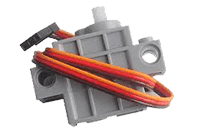
If you pull apart a servo motor, you’ll find the following inside it:
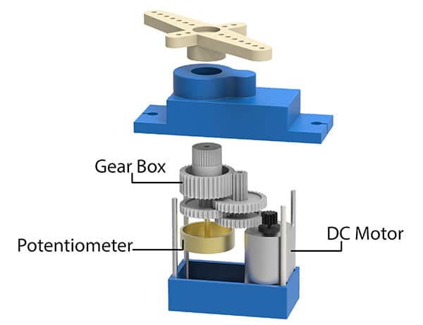
- A DC Motor
- A Potentiometer
- A gear train i.e. a series of gears that are connected such that their teeth are engaged/interconnected. (A gear can be visualized as a wheel with teeth, not the regular teeth though; sometimes more and sometimes less than 32!)
- A control circuit: This circuit is the actual brain behind the precise working of the servo. It controls how much the servo should move or rotate depending on the input it receives.
Servo Calibration
The purpose of servo motor calibration is to align the angle of your servo motor properly.
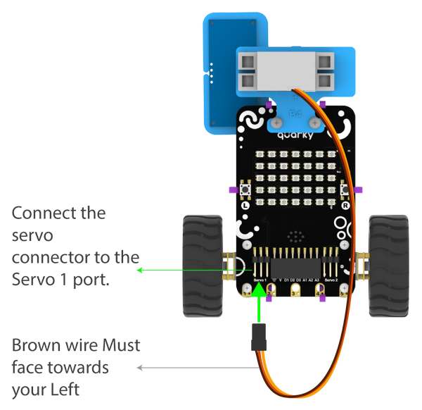
Connecting Servo to Quarky
The Servo motor will be connected to the Quarky Servo Connector. There are two servo ports on Quarky. Always make sure that the brown wire is on your left side.
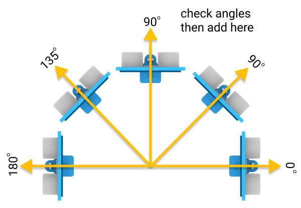
Angle Calibration
To do the calibration we have to be familiar with the servo angles.
According to the servo motor’s configuration, 90° means facing forward. Therefore, 45° is on the right, and 135° on the left, which is nothing but 45° on the left, from the forward position.
 Servo Control Blocks
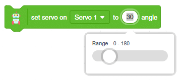
PictoBlox has one block that can be used to calibrate a servo motor:
- Set servo on () to () angle: This block is used to change the angle of the servo motor to any particular angle between 0 to 180.
We have assembled the Obstacle Avoidance Robot. We will understand how to calibrate it using this block. Follow the steps given below,
- First, detach the Ultrasonic Sensor Assembly from the servo head.
- Go to the event block and drag and drop the when green flag clicked into the scripting area.
- Next, place the set servo on () to () angle from the robot palette below the when green flag clicked block.
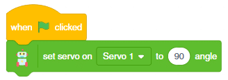
- Run the script. The servo head should get aligned properly.
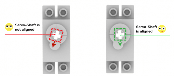
- Finally, put the Ultrasonic Assembly on the servo shaft.
Your calibration is done.
Activity: Servo Movement
Continuing with the next activity, here we’ll rotate the servo motor’s shaft at different angles, such as 0, 90, and 180 degrees.
Code:
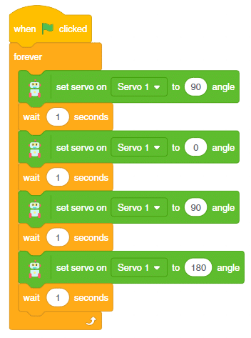
Testing:
When we click on the green flag, the servo’s shaft will continue to rotate. Try to set it on different angles and check.
Conclusion
In this lesson, we have discussed the servo motor and how to calibrate it. We have also seen how to control it using PictoBlox. We have also seen how to use it in the Obstacle Avoidance Robot. We hope that this lesson has helped you to understand the servo motor and its uses.