Introduction
Digital pins
Arduino’s digital pins offer two voltage levels: HIGH (5V) or LOW (0V). When set to LOW, a pin provides 0V to external devices, while setting it to HIGH delivers 5V, enabling triggering of relays or LED illumination. Additionally, digital pins can function as input to read data from peripheral devices or as output to power sensors and other devices. On the other hand, analog pins are used to read analog values in the form of voltage levels ranging from 0V to 5V.
Analog pins
These are the pins that are used to read the analog values from devices in the form of voltage levels between 0v to 5v
Circuit Diagram
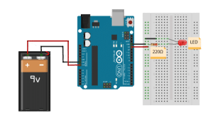
- Resistance = 220Ω
- LED+ to pin 13
- LED – to GND
Code
Now let’s connect our Arduino to Pictoblox and learn to code.
- Open Pictoblox and choose Block coding.
- Go to “boards” and select “Arduino Uno” from the list
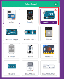
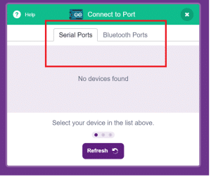
- From “connect,” choose the serial port, and then click on the “connect” button to establish the connection between Arduino Uno and your computer..
- Click on the event palette and drag “when the flag clicked.”

- From the control palette, drag the “forever” block and add it to the event block.

- From the Arduino palette, drag “set digital pin() output as ()” block into the forever block.
- Again from the control palette add the wait() block into the forever block
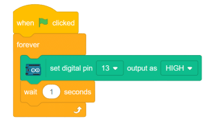
- Repeat steps 6 and 7, setting the output as LOW this time.
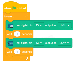
Script

Output


