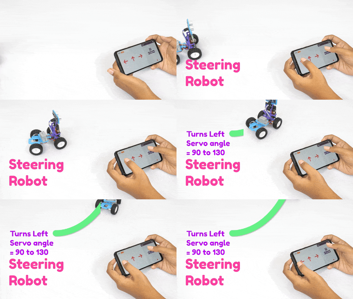
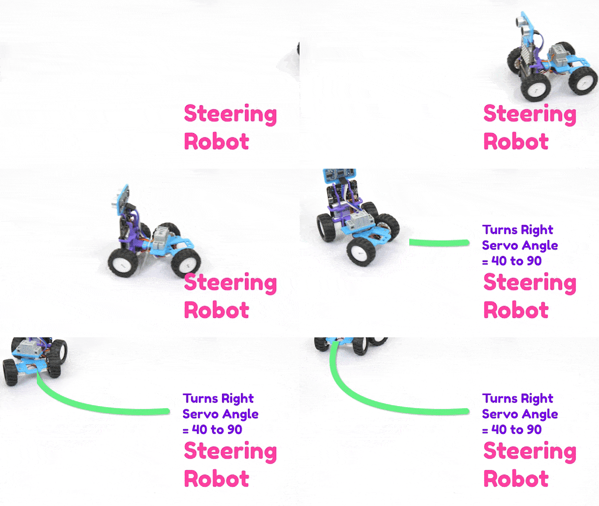
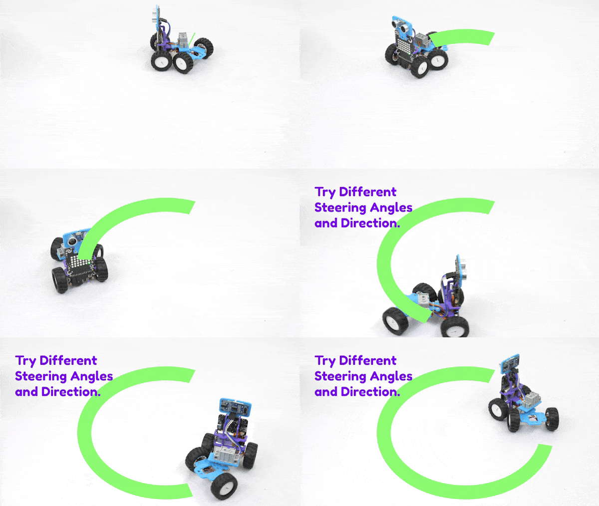
The Steering Robot is a robot that can be controlled manually and autonomously using the steering of the robot. It introduces learners to the principles and construction of steering robots. We can control its steering using arrow sprites and the keyboard arrow keys. This robot can change its direction using steering and forward or backward, respectively.
Interesting Right?! Let’s begin with assembling the robot first!
Assembly of Vertical Steering Robot
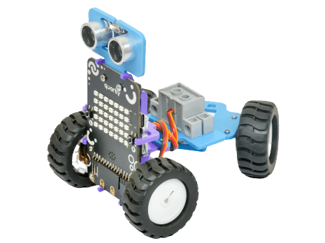
First things first, let’s see how to assemble the vertical steering robot before moving on to the activity. We are starting with the Horizontal Robot.
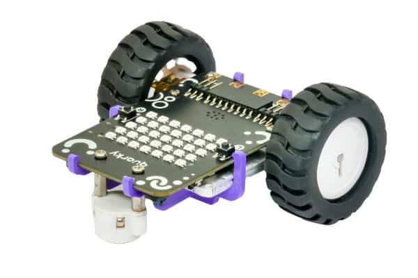
- First, detach the Castor Wheel from the Quarky Robot by removing the Bolt.
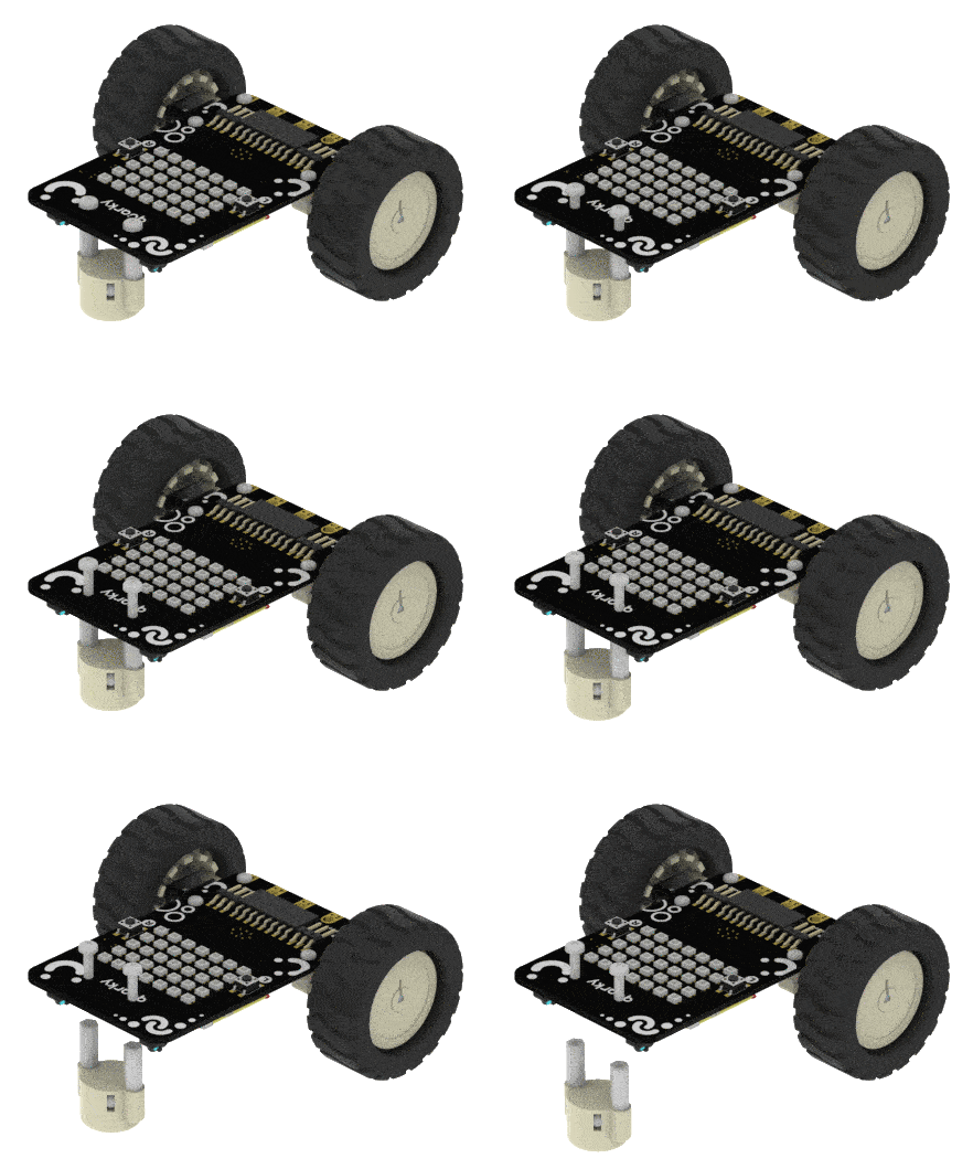
- Detach A2 from the Quarky Robot.

- Detach A1 from the Quarky Robot.
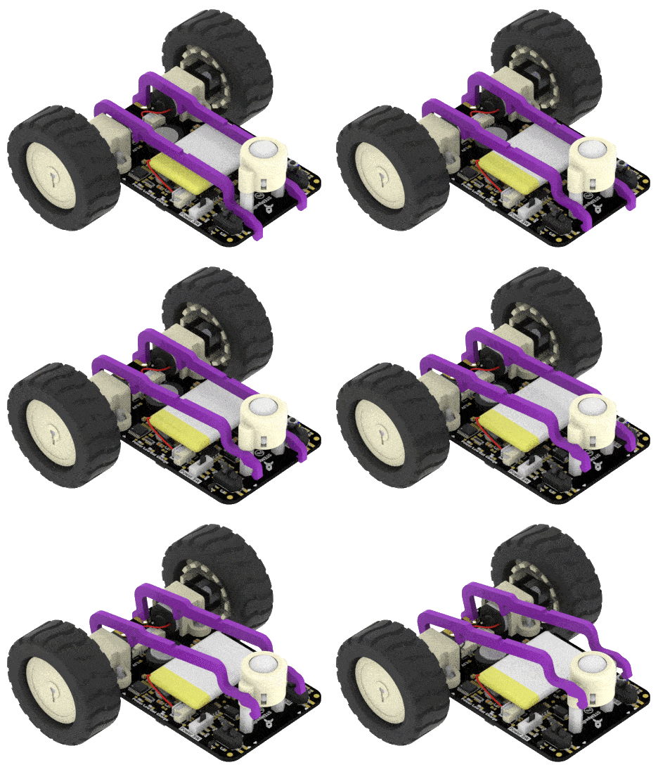
- Remove the Castor Wheel from the Robot using the Screwdriver.
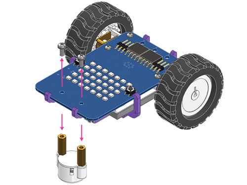
- Attach the A5 Plate with the Quarky Robot while keeping the Battery attached.
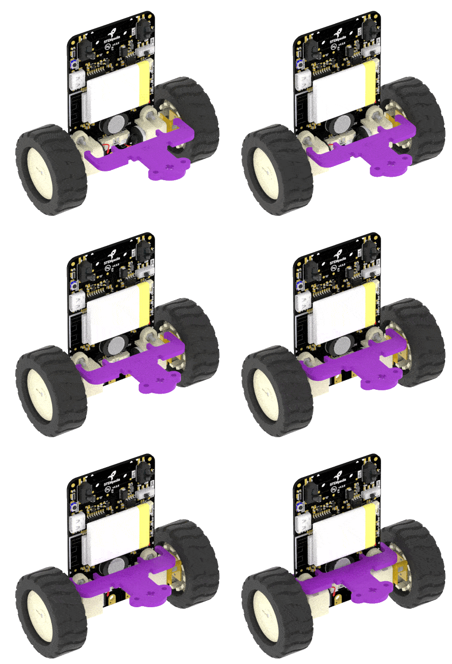
- Snap the A1 (Battery Holder) to keep the Battery safe and secure. A1 will snap automatically with the A5 Plate.
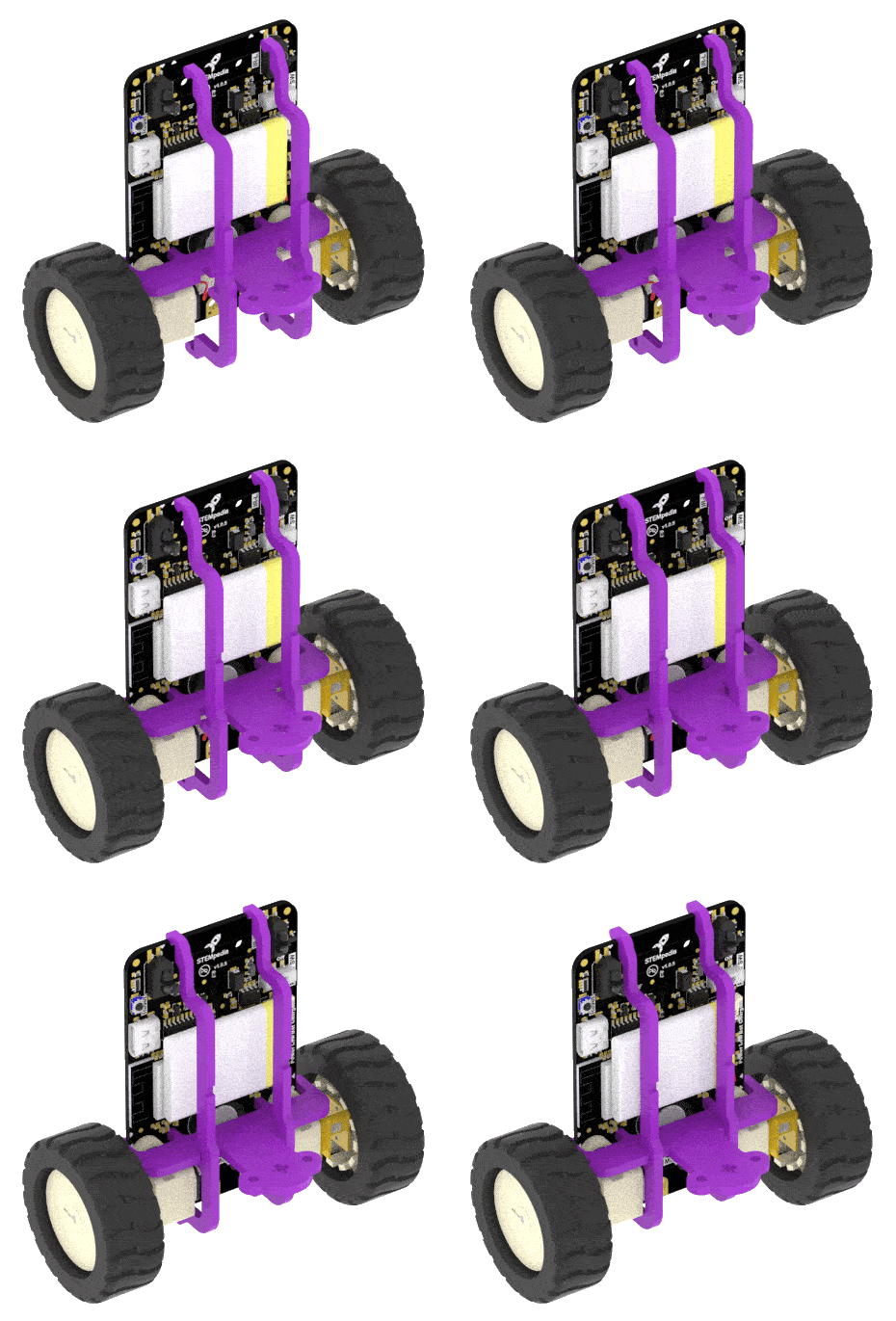
- Next, lock the battery holder with the help of the A2 link. Press the parts gently to snap them.
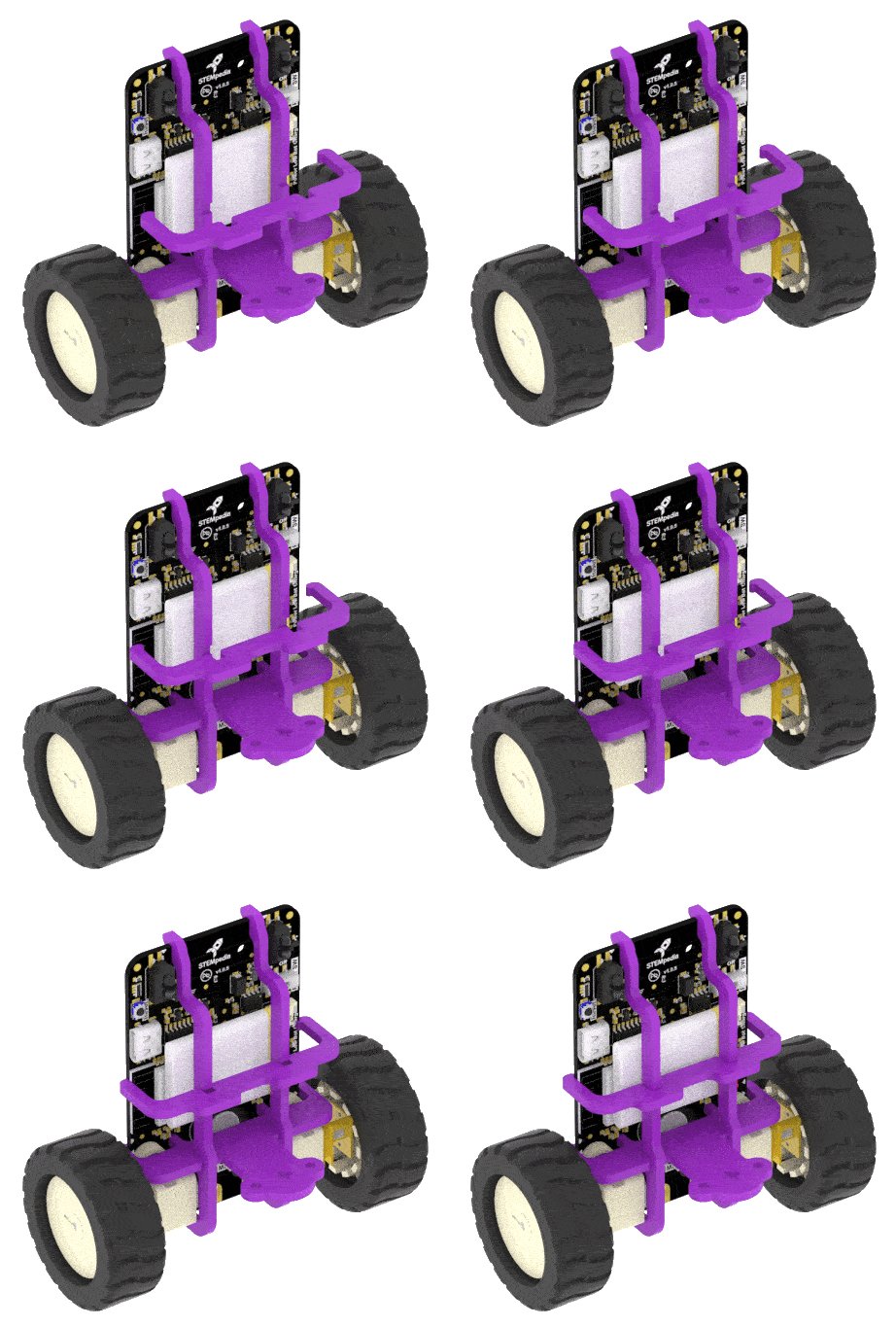
- Next, mount the B3 Plate on the top of the Robot where the Caster Wheel gets attached. Do it using M2.5 Bolt and M2.5 Nut.
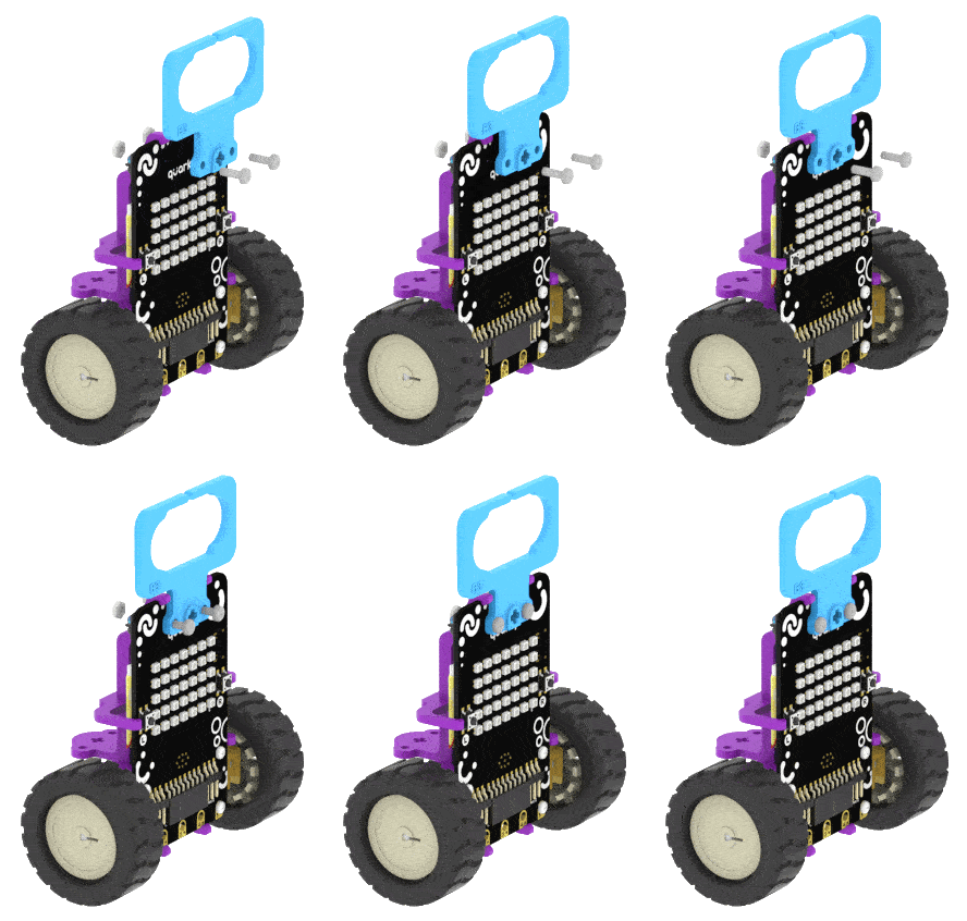
- Next, push-fit the Ultrasonic Sensor to the B3 Plate. Make sure the Sensor is facing forward.

- After that, attach the B4 Plate to A5 Plate. Fasten it using M2.5 Bolt and M2.5 Nut.
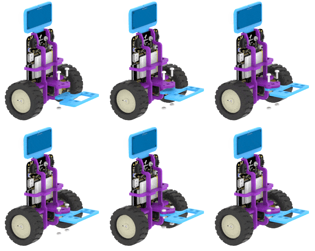
- Push-fit the Servo Motor to the B4 Plate. Ensure that its shaft is facing downwards.
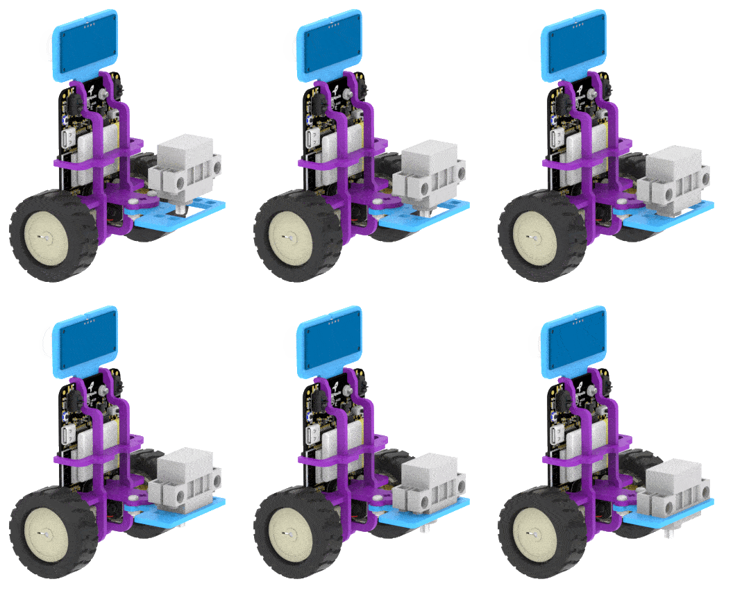
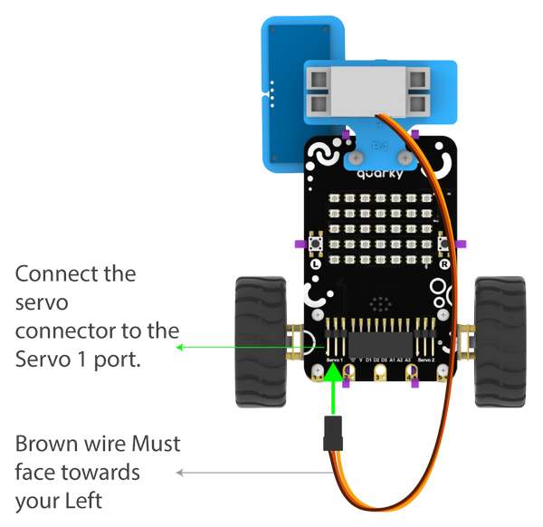
- Connect the Servo Motor to the Quarky.
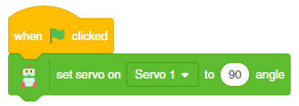
- Open PictoBlox and set the Servo Motor angle to 90 degrees. The servo head should get aligned properly.
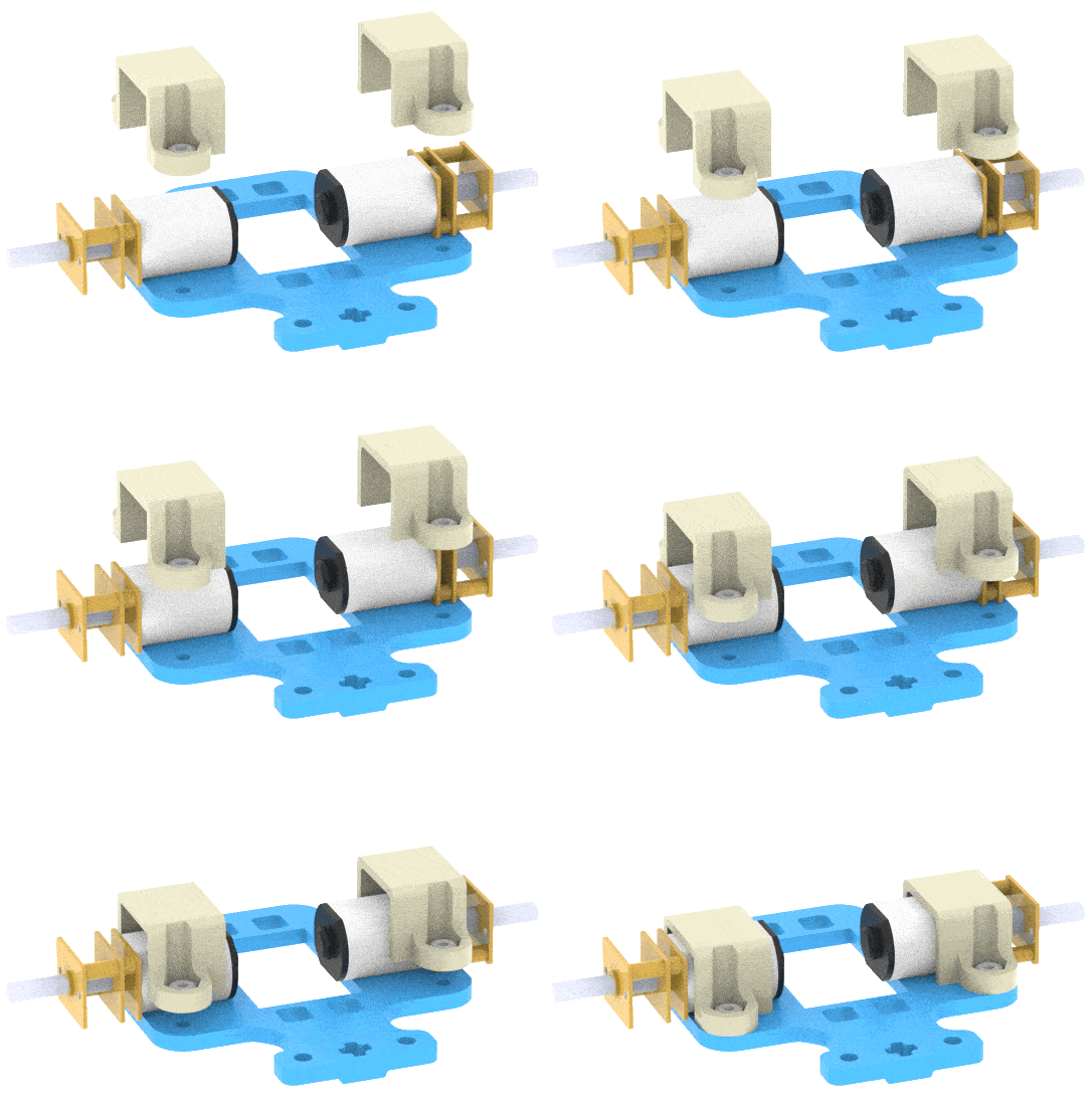
- Place the Motors on the top of the B1 Plate using the Motor Mount Bracket. Fasten it using M2 Bolt and M2 Nut that you get with Motors.
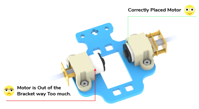
 Note: You have to make sure the Motor is appropriately mounted.
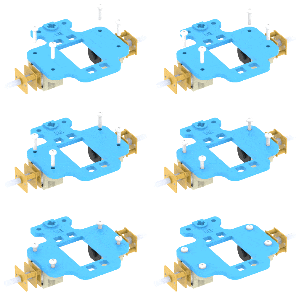
 Note: Make sure the B1 is written on the opposite side of the Motor.
- Now attach the Wheels to the Motors.
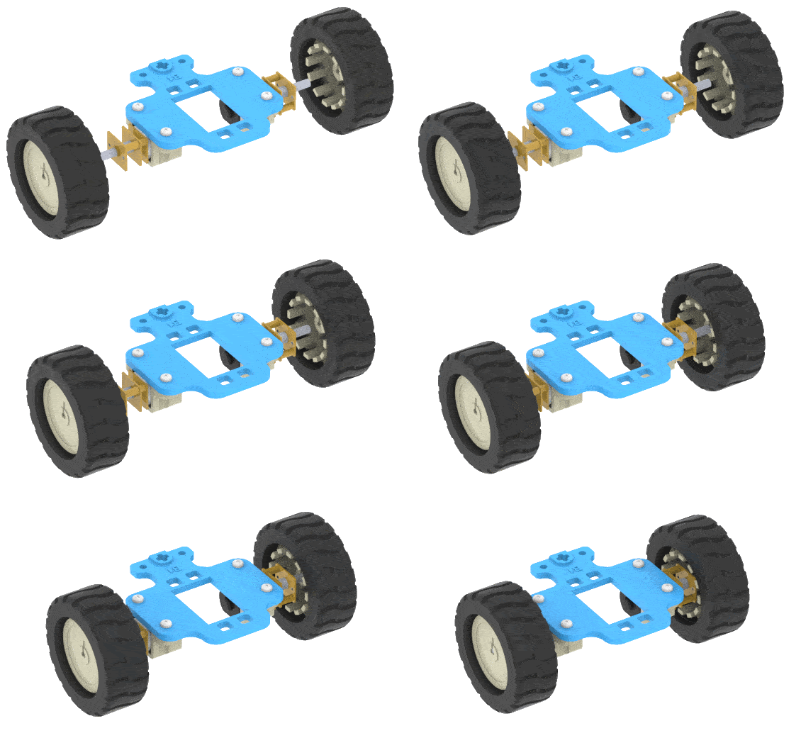
- Lastly, push-fit this Wheel Sub-assembly into the Servo Motor’s Shaft.
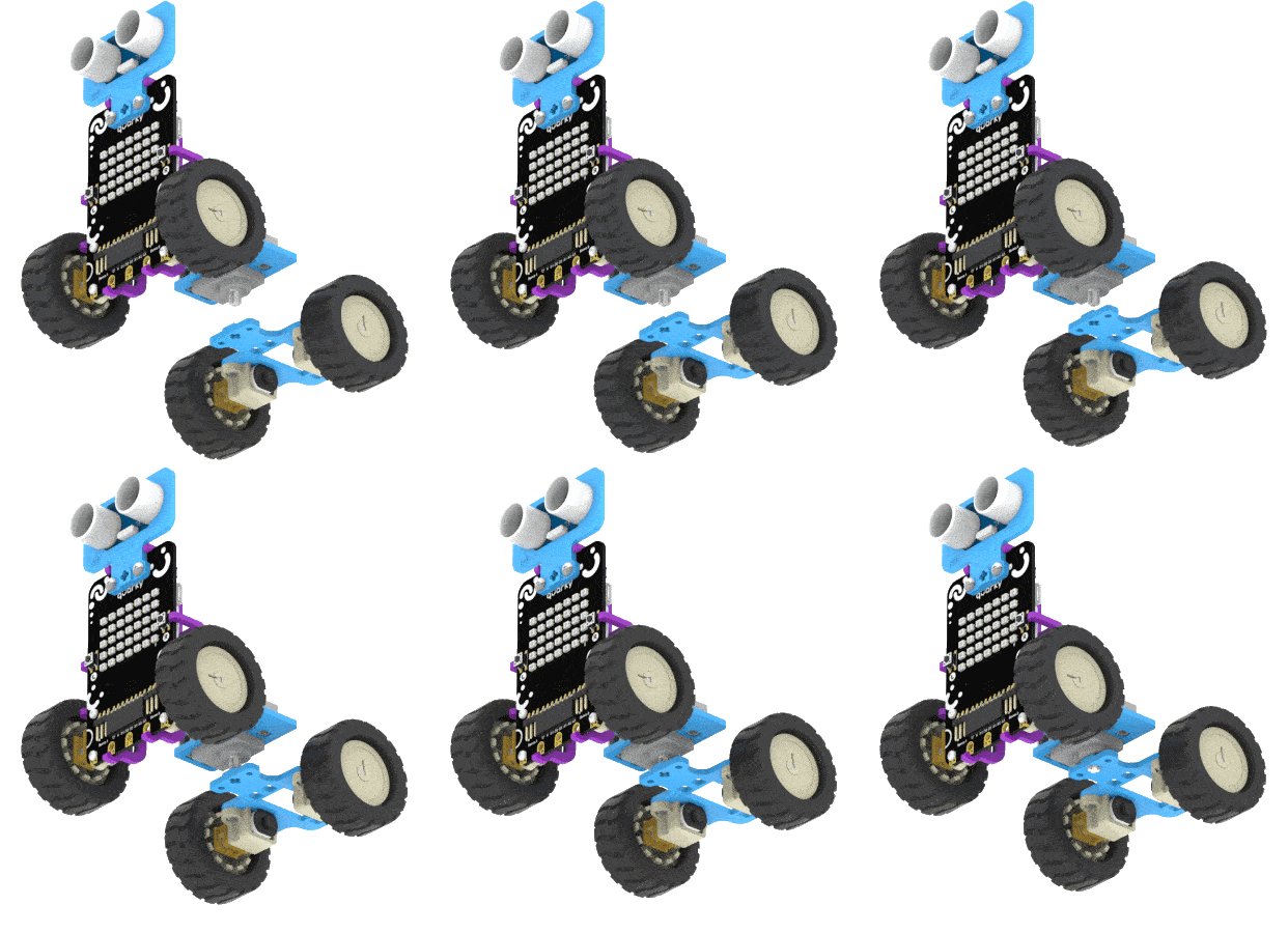
Note: Connecting the Ultrasonic sensor (Steps 7 and 8) is optional.
Wheel Motor Connection
The motor connection is tricky here. First, remove both the motors and wire from the Board. We have special wires for this circuit which connect two motors together.

Connect the two left motors and then connect the wire to the Board. Do the same for the right motors. Connections are shown in the figure.
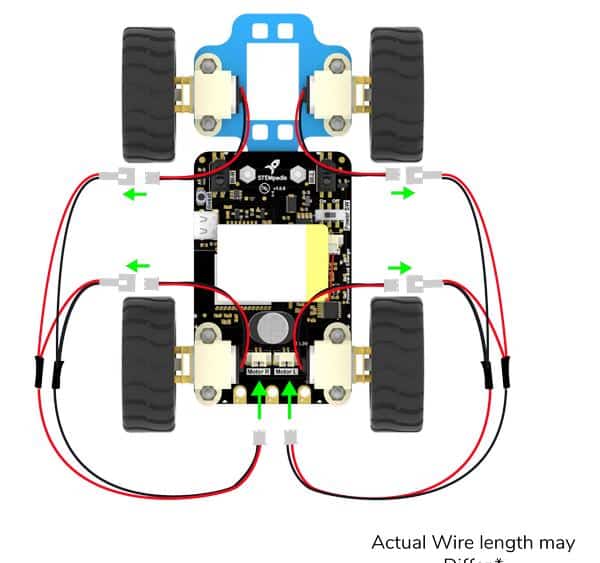
The above assembly is for reference only.
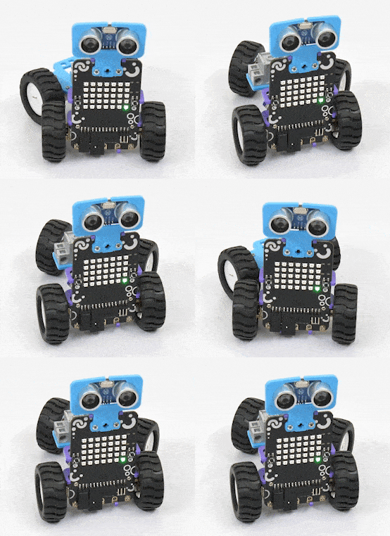
Our vertical steering robot with Ultrasonic sensors is ready!

Activity: Control Your Steering Robot
The Manually Controlled Steering Robot can go forward and backward, moreover, we can also control its steering by using arrow sprites to adjust its direction to the left, right, or center.
Now, let’s make the script for our Steering Robot!
Setting up the Stage
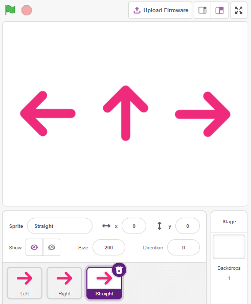
- Add three Arrow sprites to the stage from the sprite library.
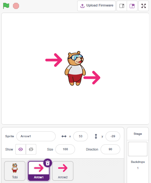
- Rename the Arrow sprites to Left, Right and Straight.
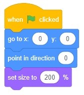
- Click on the Straight sprite and add the script to go to 0, 0 positions, point in 0degrees, and set the size to 200%.
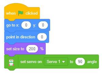
- Add the set servo on () to () angle block and set the angle to 90 degrees. This will set the steering robot straight when the code starts.
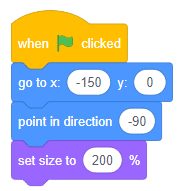
- Click on the Left sprite and add the script to go to -150 , 0 positions (go to Motion palette), point in -90 degrees (left direction), and set the size to 200%.
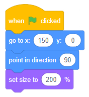
- Click on the Right sprite and add the script to go to 150, 0 positions, point in 90 degrees (right direction), and set the size to 200%.
- Finally, click on the green flag to set up the stage.
Steering Control
The steering robot has the following angles of control:
- Straight– 90 Degrees
- Left – 130 Degrees
- Right– 40Degrees
Let’s code it.
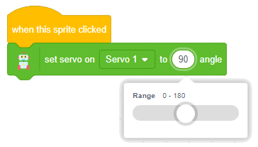
Straight Sprite
- Click on the Straight sprite and add when the sprite is clicked block from the Control palette. This will start the script when the Straight arrow is clicked.
- Add the set servo on () to () angle block and set the angle to 90 degrees.
Left Sprite
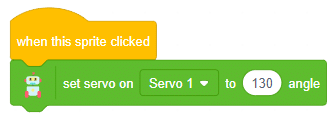
Click on the Left sprite and add a similar code as straight. This time set the angle to 130 degrees.
Right Sprite
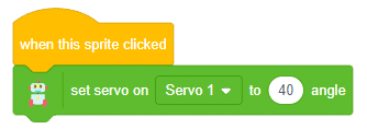
Click on the Right sprite and add a similar code as straight. This time set the angle to 40degrees.
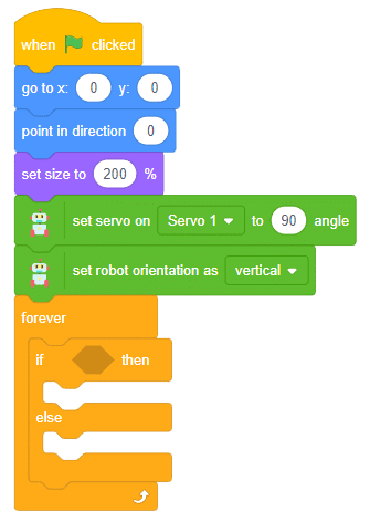
Forward-Backward Movement
- Start with Straight sprite and the main script.

- Put the set robot orientation as () block from the Robot palette. Select the orientation as vertical from the dropdown.
- Place a forever block from the Control palette.
- Now, add the if () else block from the Control palette inside the forever block.
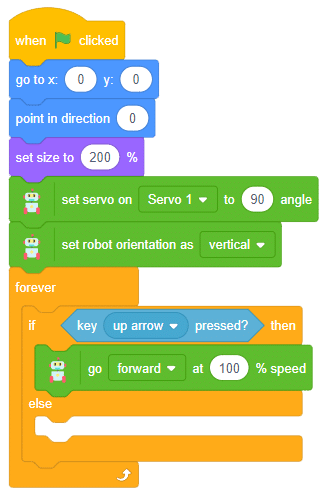
- Then, put the key () pressed block from the Sensing palette into the if-else block’s space.
- Set the key as up arrow. This statement will check whether the up arrow key is pressed or not.
- Next, drag & drop the go () at () % speed inside the if branch from the Robot palette. Set the direction as forward with a speed of 100%.
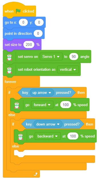
- Now duplicate this entire if () else block and put it inside the previous else branch.
- This time we’ll check the condition for the down arrow key. So, change the key to the down arrow in the ‘key() pressed’ block.
- After that, change the direction to backward in the, go () at () % speed block.
- Then, put the stop robot from the Robot palette inside the else branch.
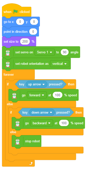
The script is complete. Test the code with the robot.
As you can see, in this robot you can control its steering by clicking on the stage arrow sprites. These arrows can change the direction of the robot in right, left, and center.
You can also move the robot in a circular motion by changing the angle.
Conclusion
In conclusion, we have successfully assembled and programmed the Quarky Steering Robot. We had a solid understanding of the steering mechanisms and their significance in robotics. We have also gained practical experience in building and programming steering robots, enhancing their skills in robotics and AI applications.

