Introduction
A servo motor is a rotary actuator that precisely controls angular position, velocity, and acceleration. It consists of a suitable motor coupled to a sensor for position feedback.
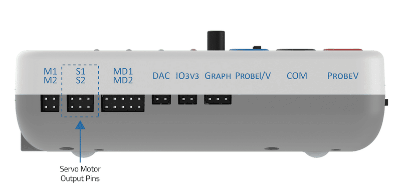
evive has two dedicated servo motor outputs pins.
Controlling Servo Angle
Servo is controlled on the concept of PWM (Pulse Width Modulation). The refresh interval (the minimum time to refresh servos in microseconds) is 20000, which means that the servo is refreshing at a frequency of 50Hz. For most of the servos, a certain range of PWM corresponds to the range of angle the servo can rotate. Minimum pulse width is the shortest time for the pulse has been HIGH and the maximum pulse width is the longest time for which the pulse is HIGH. Hence if the range of angular motor position is from 0 to 180, the minimum pulse width corresponds to 0 and the maximum pulse width corresponds to 180.
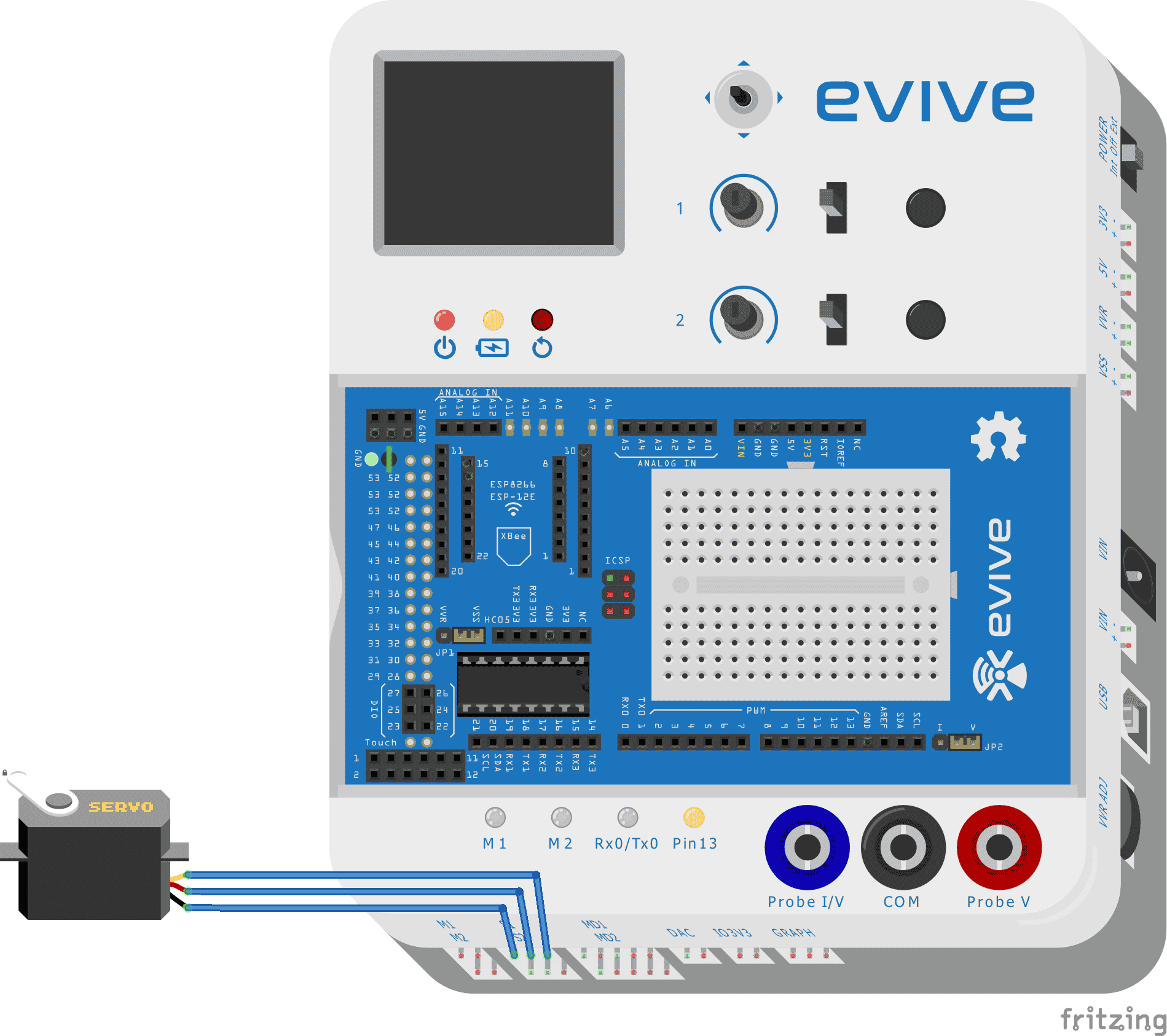
The signal pin of servo 1 is connected to digital pin 44 and servo 2 is connected to digital pin 45.
Circuit Diagram
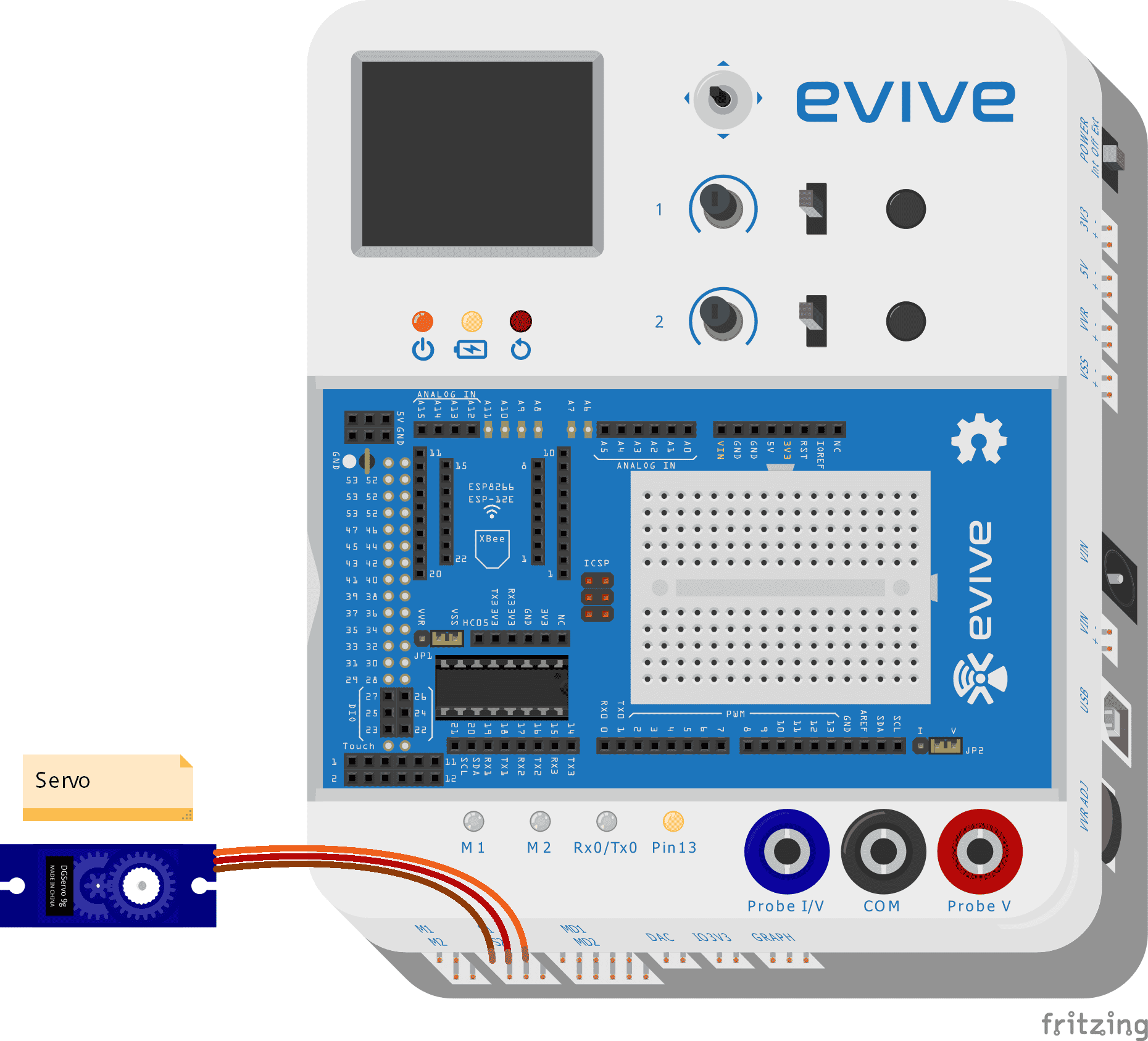
A Servo pin has three wires (Order to be connected in evive, left to right)
- Brown wire: GND
- Red wire: VCC
- Orange wire: Signal

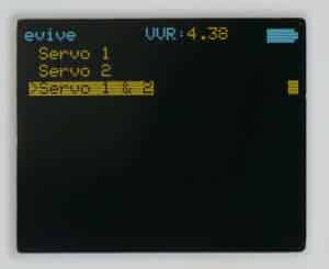
Controlling servo through the evive menu
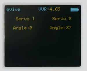
You can directly connect servo and control angle using inbuilt potentiometers using the evive menu. You just have to navigate to the control submenu, select servo and then select which servo you want to control (Servo 1 or Servo 2, or both servos).
Controlling servo using Arduino IDE
There is a servo library that can be used to control the servo motor. The available functions are provided in the table below:
| Function | Return data type | Comment |
| attach(int pin); | unit8_t | Attach the given pin to the next free channel, sets pinMode, and return channel number or 0 if failure |
| attach(int pin, int min, int max); | unit8_t | As above but also sets min and max values for writes |
| detach(); | void | |
| write(int value); | void | If the value is < 200 it’s treated as an angle, otherwise as pulse width in microseconds |
| writeMicroseconds(int value); | void | Write pulse width in microseconds |
| read(); | Integer | Returns current pulse width as an angle between 0 and 180 degrees |
| readMicroseconds(); | Integer | Returns current pulse width in microseconds for this servo (was read_us() in the first release) |
| attached(); | bool | Return true if this servo is attached, otherwise false |
Example 1
The sample code is given below which uses the library:
/*
   evive servo example
   this example demonstrates how to use servo motor for angle on evive
   input is given by POTx where x can be 1 or 2
   x is where the servo is attached
   modified on 13 September 2017
   by Nihar Shah, Agilo Research.
*/
#include<evive.h>
Servo myservo;  // create servo object to control a servo
int angle=0;
void setup() {
  myservo.attach(SERVO1_ATTACH);  // attaches the servo on pin S1 to the servo object
}

void loop() {
  angle = analogRead(POT1);            // reads the value of the potentiometer (value between 0 and 1023)
  angle = map(angle, 0, 1023, 0, 180);     // scale it to use it with the servo (value between 0 and 180)
  myservo.write(angle);                  // sets the servo position according to the scaled value
  delay(15);                           // waits for the servo to get there
}
Example 2: Controlling Servo Angle using Joystick
In the following example, I will be showing you how to control servo through channel 1. Given below is the circuit diagram:
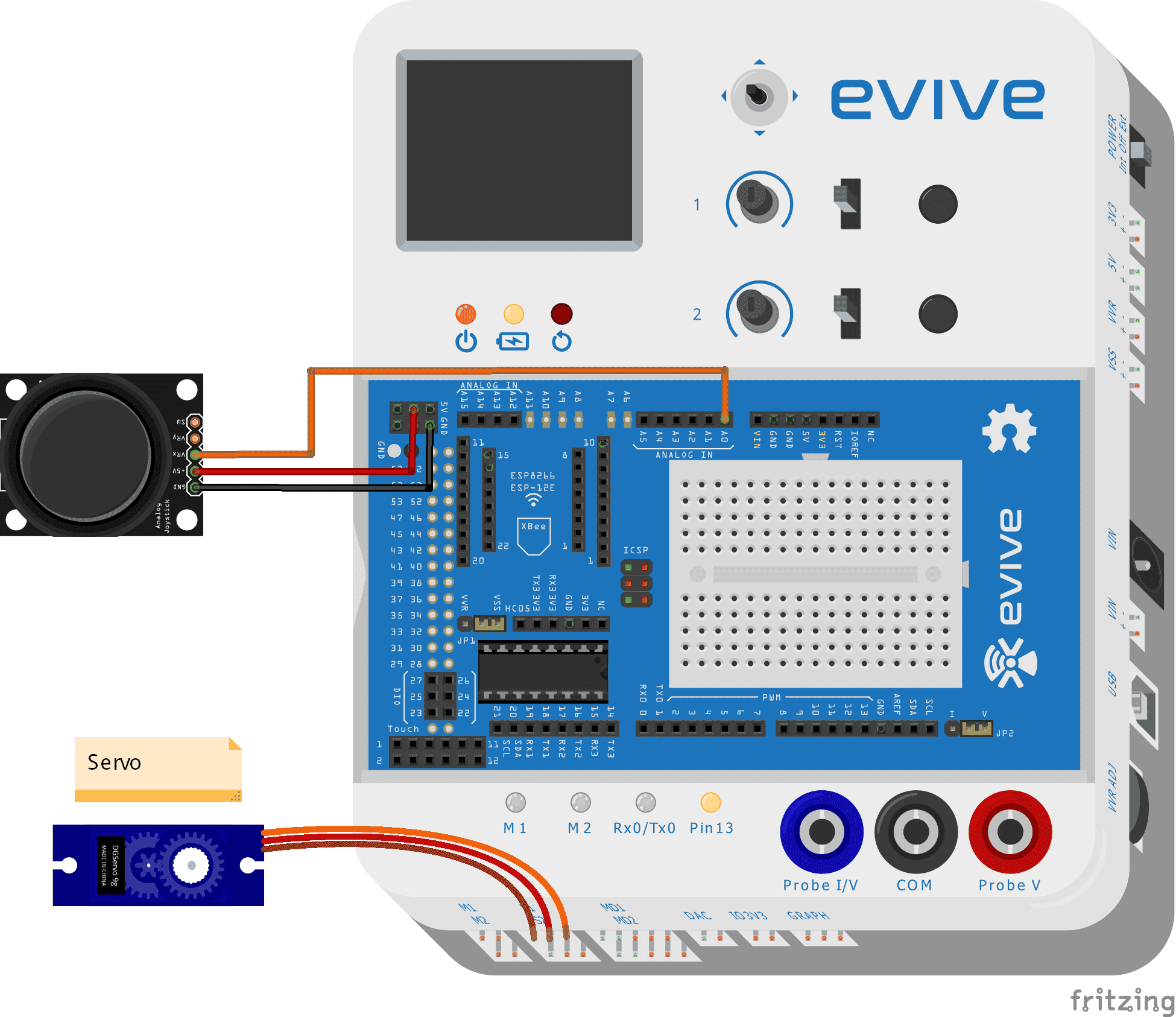
A Servo pin has three wires (Order to be connected in evive, left to right)
- Brown wire: GND
- Red wire: VCC
- Orange wire: Signal
A Joystick has 5 pins:
- Ground
- 5V
- VRx: X position connects to Analog pin 0
- VRy: Y position
- SW: Z press
How does Joystick work?
The joystick has 2 potentiometers and a switch. A potentiometer has a wiper sliding on a resistive strip. If the wiper is close to GND, it outputs 0V, and if it is close to VCC or 5V, it outputs 5V. In Arduino IDE, if the wiper is close to GND you get 0 value and if it is close to VCC, you get 1023. Hence you get approx. 512 when the joystick is at the default position.
Code
#include <servo.h>

double Angle;
double Potentiometer;
Servo servo_3;

void setup(){
 Angle = 0;
 pinMode(A0,INPUT);
 servo_44.attach{44); // init pin
}

void loop(){
 Potentiometer = analogRead(A0);
 Angle = ((Potentiometer) * (180)) / (1023);
 servo_44.write(Angle); // write to servo
 delay(50);
}
Conclusion
In conclusion, servo motors are an excellent choice for precisely controlling angular position, velocity, and acceleration. They are easy to use and can be controlled directly through evive‘s menu or using the Arduino IDE and servo library. Controlling the servo angle using the joystick is also possible, as shown in the example code. With a bit of creativity, servo motors can be used in many interesting projects!