Introduction
evive has 1 single-color and 2 dual-color programmable LEDs, along with fixed LEDs for serial communication, power indication, and battery charging status.
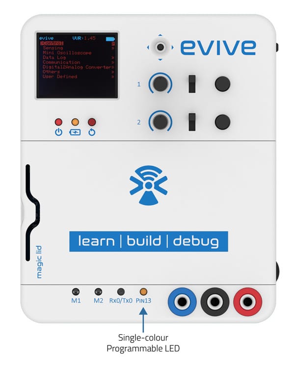
Single Colour Programmable LED
A single color LED is connected to digital pin 13 of Arduino Mega, which is programmable and can be controlled via digitalWrite() or analogWrite() functions.
The following code illustrates the use of digitalWrite() to control LED:
/*
  evive Single Colour Blink Code
  Turns on an LED on for one second, then off for one second, repeatedly.

  Modified by Pankaj Kumar Verma
  on 25 Dec, 2016
*/

int LEDpin = 13;

void setup() {
  // initialize digital pin LEDpin as an output.
  pinMode(LEDpin, OUTPUT);
}

void loop() {
  digitalWrite(LEDpin, HIGH);         // turn the LED on (HIGH is the voltage level)
  delay(1000);                        // wait for a second
  digitalWrite(LEDpin, LOW);          // turn the LED off by making the voltage LOW
  delay(1000);                        // wait for a second
}
The following code illustrates the use of analogWrite() to control LED:
/*
evive Single Colour Blink Code
Turns on an LED on for one second, then off for one second, repeatedly.
Modified by Pankaj Kumar Verma
on 25 Dec, 2016
*/
int LEDpin = 13;
void setup() {
// initialize digital pin LEDpin as an output.
pinMode(LEDpin, OUTPUT);
}
void loop() {
int a = 0;
for(a = 0; a < 255; a = a+5) { analogWrite(LEDpin, a); delay(25); } for(a = 255; a > 0; a = a-5)
{
analogWrite(LEDpin, a);
delay(25);
}
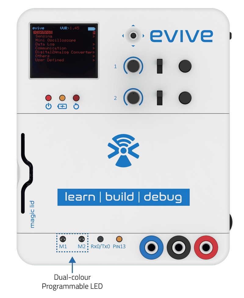
}Dual-colour Programmable LED
Two dual-color programmable LEDs are attached to digital pins 28 and 29 for the first LED and digital pins 30 and 31 for the second LED. By controlling the output of one of the pin, you can control one color of the LED and by controlling the second color. Both the LEDs are common cathode LEDs, which means that the common terminal is GND and when the other pins are given HIGH, the LED glows.
The following program illustrates how to use a dual-color LED.
/*
 evive inbuit bi-directional LED code

 Bi-directional LED 1 is connected to digital pin 28 and 29.
 Bi-directional LED 2 is connected to digital pin 30 and 31.

 This code demonstrates how to use evive inbuilt biderectional LEDs.
 The code turns on and off a bi-dectional LED connected to digital
 pin 28 and 29, when sliding the slideswitch to either sides connected to digital pin 40 and 41.

 Created by Pankaj Kumar Verma
 On 12 Dec, 2016

 This example code is in the public domain.

 */

// set pin numbers:
int slidePin1 = 40;               // the number of the slideswitch 1 pin 1
int slidePin2 = 41;               // the number of the slideswitch 1 pin 2

//int ledPin1 =  28;              // the number of the LED 1 pin 1
//int ledPin2 =  29;              // the number of the LED 1 pin 2
int ledPin1 =  30;                // the number of the LED 2 pin 1
int ledPin2 =  31;                // the number of the LED 2 pin 2

// Note: This code is meant to run for only one bi-directional LED. Please initialise only one bi-directional LED.

int buttonState1 = 0;             // variable for reading the pushbutton pin 1 status
int buttonState2 = 0;             // variable for reading the pushbutton pin 2 status

void setup() {
  // initialize the LED pins as an output:
  pinMode(ledPin1, OUTPUT);
  pinMode(ledPin2, OUTPUT);
  // initialize the slideswitch pins as an input:
  pinMode(slidePin1, INPUT);
  pinMode(slidePin1, INPUT);
  // open serial port, set data rate at 9600 bps:
  Serial.begin(9600);
}

void loop() {
  // read the state of the pushbutton value:
  buttonState1 = digitalRead(slidePin1);
  buttonState2 = digitalRead(slidePin2);

  // check if the slideswitch is in state 1.
  // if it is, the buttonState1 is HIGH:
  if (buttonState1 == HIGH) {
    // print on serial monitor
    Serial.println("The slideswitch is in state 1");
    delay(100);
    // turn LED leg 1 on:
    digitalWrite(ledPin1, HIGH);
    // turn LED leg 2 off:
    digitalWrite(ledPin2, LOW);
  }

  // check if the slideswitch is in state 2.
  // if it is, the buttonState2 is HIGH:
  else if (buttonState2 == HIGH) {
  // print on serial monitor
  Serial.println("The slideswitch is in state 2");
  delay(100);
  // turn LED leg 1 off:
  digitalWrite(ledPin1, LOW);
  // turn LED leg 2 on:
  digitalWrite(ledPin2, HIGH);
  }

  else {
  // turn LED leg 1 off:
  digitalWrite(ledPin1, LOW);
  // turn LED leg 2 off:
  digitalWrite(ledPin2, LOW);
  }
}
Non-Programmable LEDs:
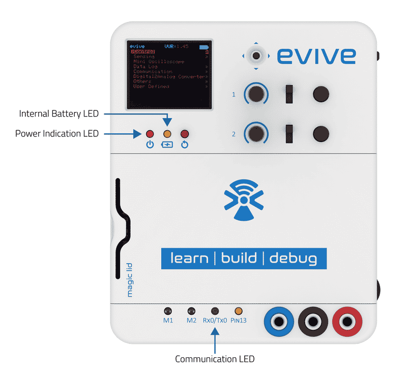
- Serial Communication LED: evive has 4 serial communication channels. For the first channel, a dual-colour LED is connected, which glow when the communication happens from the channel.
- Power Indication LED: This LED glows when evive is powered via any source (Internal battery or external power source).
- Power Indication LED: This LED constantly glows when the internal battery is charging and blinks when there is no internal battery connected to evive.
Conclusion
This lesson has provided an overview of the LEDs available on evive and how to use them. We have seen that evive has two types of LEDs: programmable and non–programmable. The programmable LEDs can be controlled using digitalWrite() or analogWrite() functions and the non–programmable LEDs indicate the status of serial communication, power indication, and battery charging. Thus, evive provides many possibilities for visual feedback and interaction.