Introduction
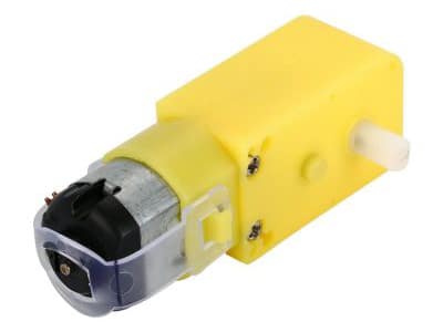
The motors that run on direct current are termed DC motors. The current that constantly flows in one direction is called direct current (DC).
There are two characteristics of DC motor that can be controlled:
- Direction: We can control the direction of rotation of the motor by reversing the direction of the voltage applied at its terminal. For that, a motor driver is needed. However, evive has an in-built motor driver hence there is no need for the extra circuit of the motor driver.
- Speed: We can control the voltage of the motor by varying the supply voltage to it.
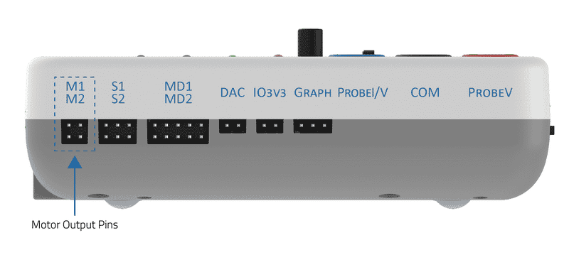
evive has two inbuilt motor control units with which you can control motors having a current limit of 1A each. It uses an SN754410NE Quad H-Bridge IC to control two DC Motors.
SN754410NE
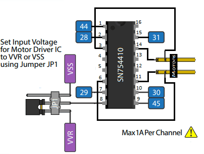
If you look at the SN754410NE chip, you will notice a u-shaped notch at one end. This helps you identify pin 1.
- Pin 4, 5, 12, and 13 are connected to the ground.
- In the image of the motor driver numbers shown in the blue box determines the digital pins on evive to which the motor driver is connected.
- Pin 2,7,10 and 15 are input pins of the motor driver, when logic 1 (5v) signal is applied to them then outputs 3,6,11, and 14 respectively also show an output voltage.
- The output voltage available at output pins is dependent on the voltage applied to Enable 1 and Enable 2 pins.
- Enable 1 and Enable 2 pins are given a PWM signal from evive. Depending upon the value of the PWM signal applied the voltage supplied at the Vcc2 pin of the IC is mapped and given as an output on the output pins of the driver IC.
- Enable 1 controls the voltage value that will appear on pin 3 and pin 6 of IC when the signal is given to pin 2 and pin 7 respectively.
- Similarly, Enable 2 controls the voltage value that will appear on pin 14 and pin 10 when the signal is applied to pin 15 and pin 9 respectively. Hence these factors decide the supply voltage at motors connected to evive.
Consider one example if Enable 1 is given an analog input of 2.5V from the PWM pin of evive and an input signal is given on input pins 2 and 7 of IC then the voltage that appears across the output pins 3 and 6 respectively will be half of the voltage applied at Vcc2 i.e Vcc2/2 on driver IC. The same will be the case for Enable 2 and the remaining input and output pins of the IC.
VVR vs VVS
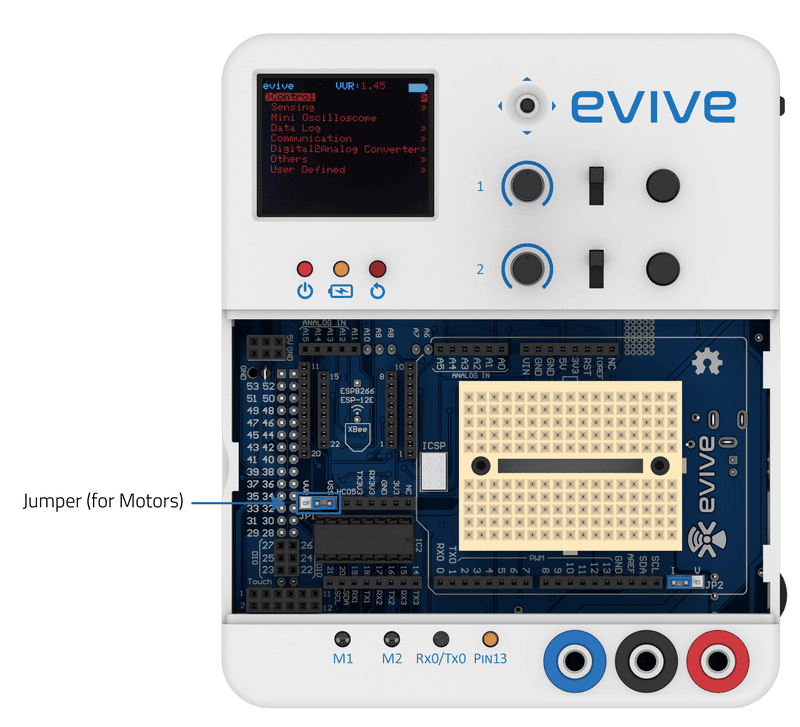
The maximum voltage that a motor gets on evive is the voltage value that is applied to the motor driver unit of evive. Motor driver unit can be powered through VVR as well as VSS supply of evive. To check which power unit of evive powers the driver, check the location of jumper JP1 on evive. If it is on the VVR side then the driver circuit gets the voltage value set by the VVR (Variable Voltage) knob of evive. If it is on the VSS side, the voltage supply to the driver circuit is the same as the supply given to evive. This means if we power evive by a 12V adapter then driver circuit gets 12V given that the JP1 jumper is on the VSS side. And if JP1 is on the VVR side then the supply to the driver circuit will be any value in the range of 0V to 12V depending upon the position of the knob VVR on evive.

Controlling motor using evive menu-based system
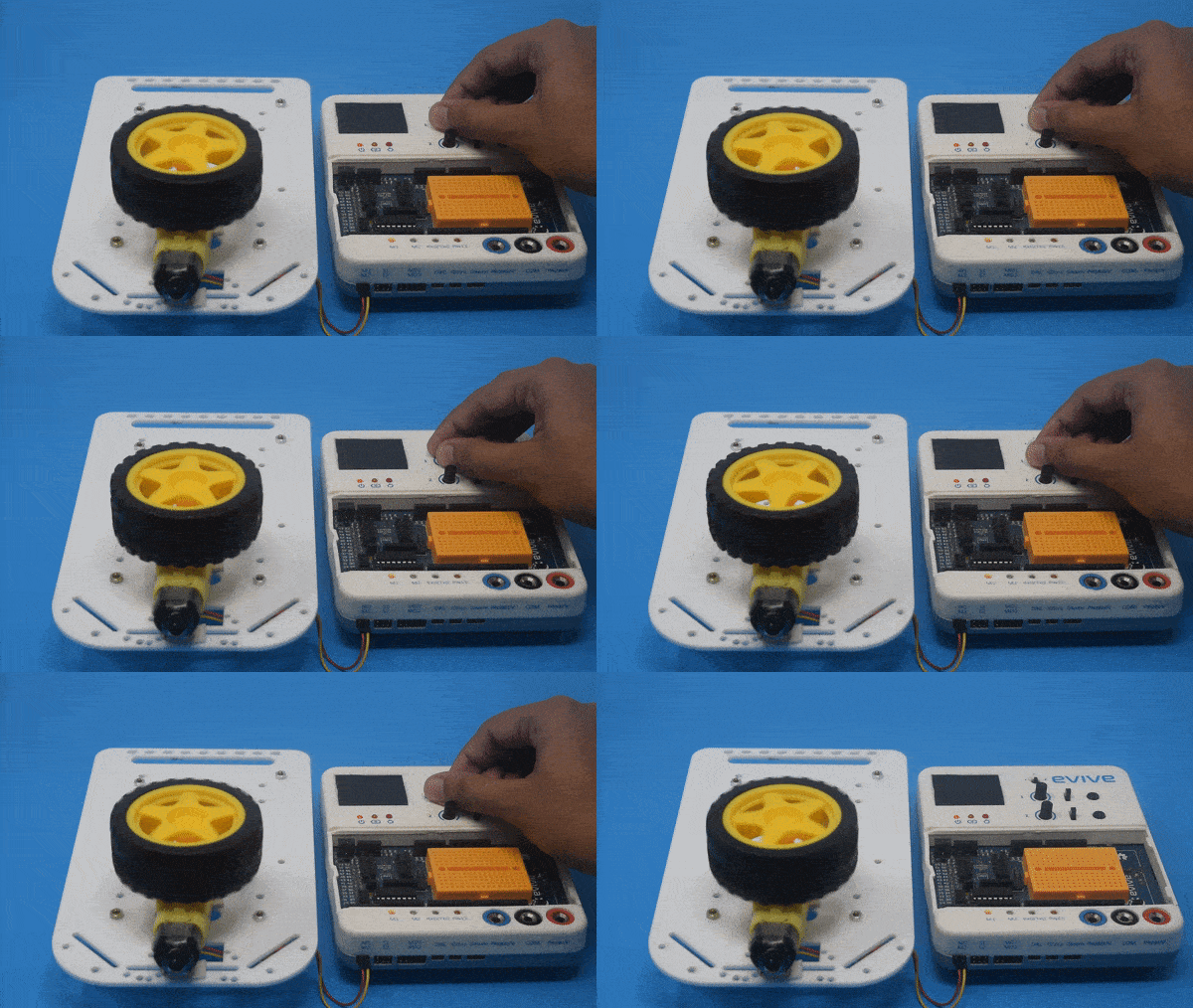
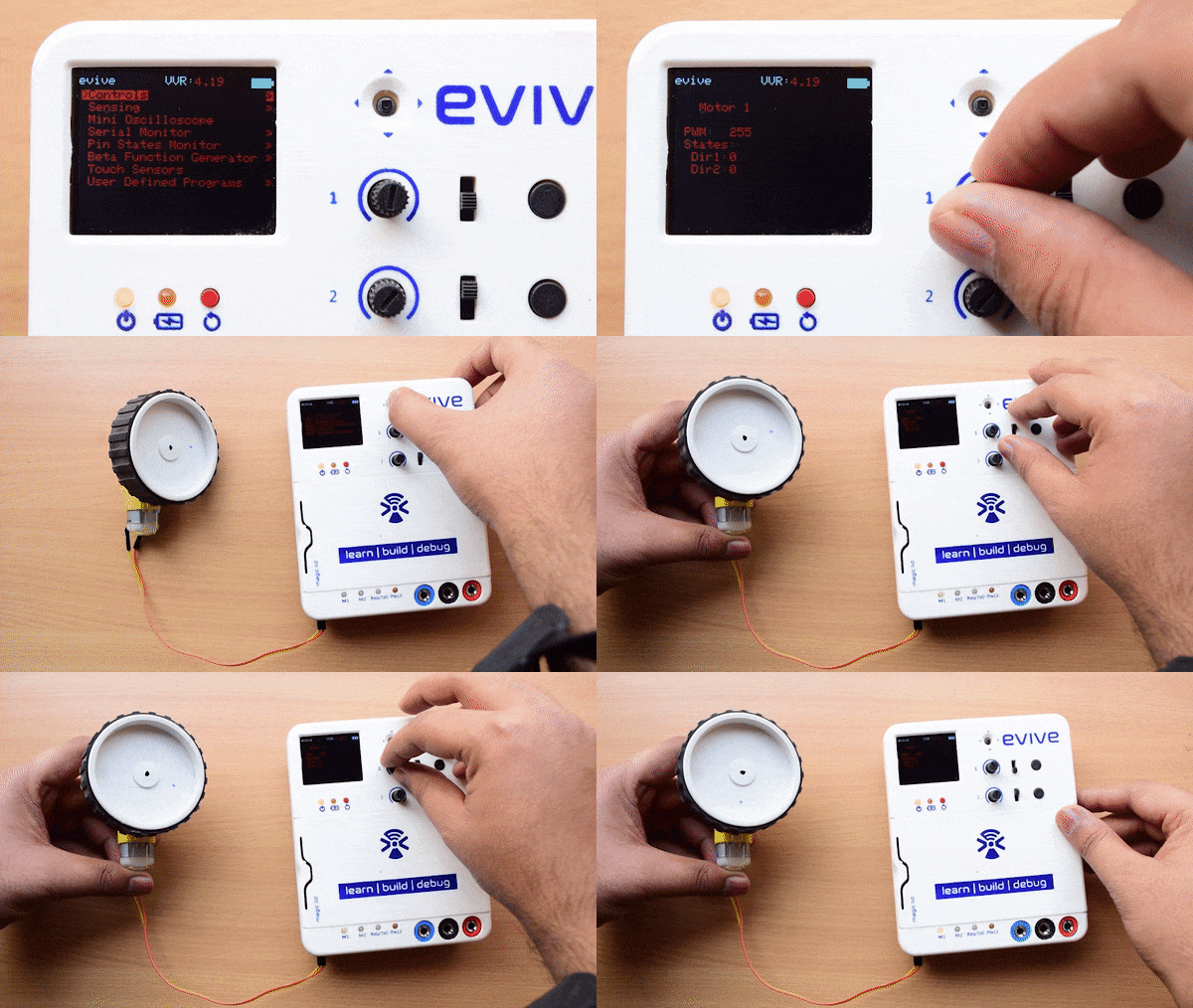
You can control or test your motors through an evive menu-based system. You have to just navigate into control, select the motor and then select which motor output you want to use (Motor 1, Motor 2, or both Motor 1 and Motor 2).
Using inbuilt potentiometers, you can control the PWM of the motors, and using slide switches you can control the state of the motor (CW, CCW, or free state).
Controlling motor using Arduino IDE
Library Variables
| Variable | Type | Comment |
| dir1_pin | Integer | Stores pin no of direction1 |
| dir2_pin | Integer | Stores pin no of direction2 |
| pwm_pin | Integer | Stores pin no of PWM pin |
| dir1 | Integer | Stores value of DIR1PIN as 1 or 0 |
| dir2 | Integer | Stores value of DIR2PIN as 1 or 0 |
| pwm | Integer | Stores the PWM value is given to the motor |
| mean_speed | Integer | The value to which motor moves when speed=100% |
| speed | Float | Speed of the motor in the percentage of mean speed |
| damping | Integer | To be changed later by trial |
Library Functions
| Function | Comment |
| Motor(); | Constructor |
| Motor(int Dir1,int Dir2,int Pwm); | Constructor with attachments of pins |
| void attachMotor(int Dir1,int Dir2,int Pwm); | Attachments of pins |
| void moveMotor(int Pwm); | Positive for CW and negative for CCW |
| void moveMotor(int Dir1,int Dir2,int Pwm); | dir1 and dir2 can be 1 or 0,PWM can only be positive for CW |
| void stopMotor(); | By default stop, motor will lock motor |
| void lockMotor(); | To lock the motor |
| void freeMotor(); | Free the motor |
| void setMeanSpeed(int Speed); | Sets the mean speed with which motor moves when speed=100% |
| void setMotorSpeed(int Speed); | Positive for CW and negative for CCW. Speed in the percentage of mean speed |
| void setMotorSpeed(int Dir1,int Dir2,int Speed); | dir1 and dir2 can be 1 or 0 |
| void changePWM(int Pwm); | Just to change the PWM in whatever direction the motor was moving |
| void changeSpeed(int Speed); | Just to change the speed (In percentage) not the direction |
| int getDirection(); | +1 for CW and -1 for CCW and 0 for free or locked |
| int isFree(); | +1 for free and 0 for not free |
| int isLocked(); | +1 for locked and 0 for not locked |
| int getSpeed(); | Returns speed in % of mean speed |
| int getPWM(); | Returns positive for CW and negative for CCW. |
| void startSmoothly(int Speed); | Positive for CW and negative for CCW. |
| void stopSmoothly(); |
Example 1: Automated Motion
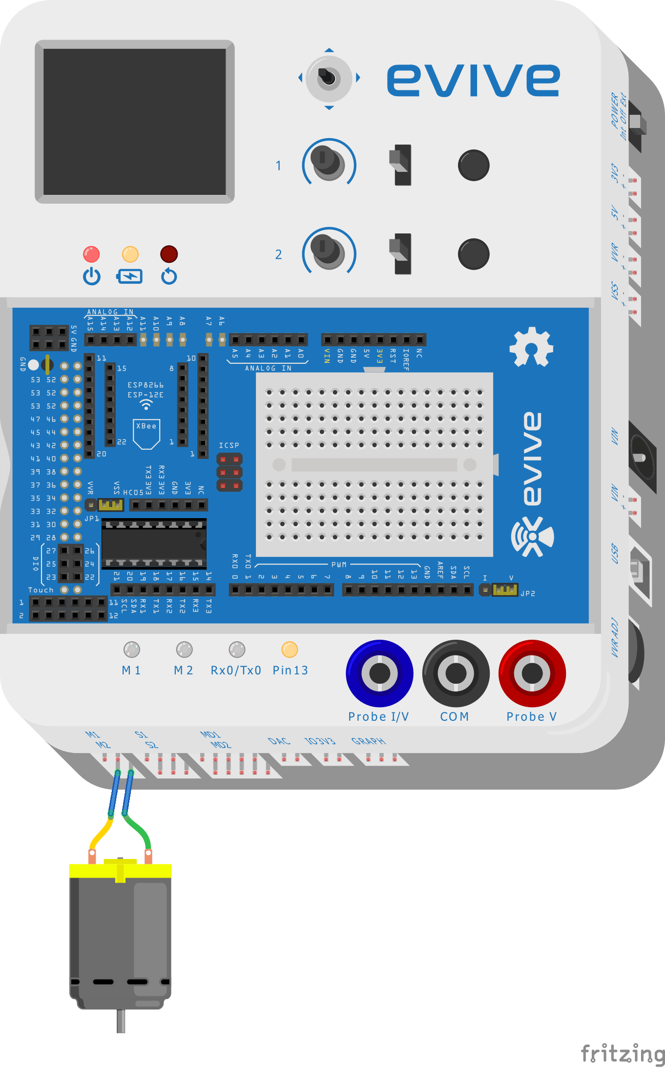
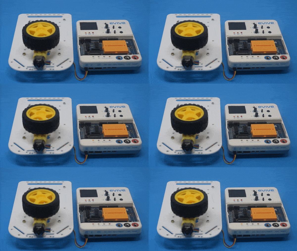
In this example, we will be controlling a DC motor through channel M1. Below is the sequence of events:
- The motor rotates for 1 second in a clockwise direction with 150 PWM.
- The motor stops for 1 second.
- The motor rotates for 1 second in a counter-clockwise direction with 150 PWM.
- Motor free for 1 second.
- Repeat.
Below is the Arduino IDE sketch:
/*
   evive motor control through motor library

   For Motor 1: Dirction digital pins are MOTOR1_D1 and MOTOR1_D2, and PWM pin is digital pin MOTOR1_EN
   For Motor 2: Dirction digital pins are MOTOR2_D1 and MOTOR2_D2, and PWM pin is digital pin MOTOR2_EN

   This code demonstrates how to use motor library to start motor, stop motor, control its direction of rotation and speed..
   Here a dc motor is plugged in channel M1 on evive. And that motor is rotated clockwise and anti-clockwise at constant pwm.
   Created by Nihar Shah.
   This code is in public domain.
   Explore more: https://thestempedia.com/tutorials/dc-motor-driving/
*/

#include <evive.h>
Motor Motor1 = Motor(MOTOR1_D1, MOTOR1_D2, MOTOR1_EN);

void setup() {
  // put your setup code here, to run once:

}

void loop() {

  //Rotate motor in CW direction with PWM 200
  Motor1.moveMotor(200);
  delay(1000);

  // Stop Motor
  Motor1.freeMotor();
  delay(1000);

  // Rotate motor in CCW direction with PWM -200
  Motor1.moveMotor(-200);
  delay(1000);

  // Stop Motor
  Motor1.freeMotor();
  delay(1000);
}
Example 2
In the above example we rotated the motor in different directions at constant PWM now we will vary the PWM applied to the motor with help of a potentiometer to see the change in the speed of the motor.
/*
   evive motor control through motor library

   For Motor 1: Dirction digital pins are MOTOR1_D1 and MOTOR1_D2, and PWM pin is digital pin MOTOR1_EN
   For Motor 2: Dirction digital pins are MOTOR2_D1 and MOTOR2_D2, and PWM pin is digital pin MOTOR2_EN

   This code demonstrates how to use motor library to start motor, stop motor, control its direction of rotation and speed..
   Here a dc motor is plugged in channel M1 on evive. And that motor is rotated clockwise and anti-clockwise at constant pwm.
   Created by Nihar Shah.
   This code is in public domain.
   Explore more: https://thestempedia.com/tutorials/dc-motor-driving/
*/

#include <evive.h>
Motor Motor1 = Motor(MOTOR1_D1, MOTOR1_D2, MOTOR1_EN);

void setup() {
  // put your setup code here, to run once:

}

void loop() {

  //Rotate motor in CW direction with PWM 200
  Motor1.moveMotor(200);
  delay(1000);

  // Stop Motor
  Motor1.freeMotor();
  delay(1000);

  // Rotate motor in CCW direction with PWM -200
  Motor1.moveMotor(-200);
  delay(1000);

  // Stop Motor
  Motor1.freeMotor();
  delay(1000);
}
Conclusion
In this lesson, we have learned about DC motors, their characteristics, and how to control them using evive. We have discussed the motor driver IC SN754410NE and its functionality. We have also seen how to control a motor using the evive menu–based system and the Arduino IDE. Finally, we have looked at two examples of controlling a DC motor using evive. This lesson has provided a comprehensive introduction to the basics of DC motor control.

