Introduction
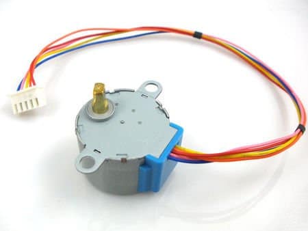
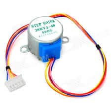
Stepper Motor is a motor controlled by a series of electromagnetic coils. The center shaft has a series of magnets mounted on it, and the coils surrounding the shaft are alternately given current or not, creating magnetic fields which repulse or attract the magnets on the shaft, causing the motor to rotate. In this tutorial, we will be using “28-BYJ48” Unipolar stepper motor
There are two basic types of stepper motors
- Unipolar stepper motor
- Bipolar stepper motor
Unipolar Stepper Motor
The unipolar stepper motor has five or six wires and four coils (actually two coils divided by center connections on each coil). The center connections of the coils are tied together and used as the power connection. They are called unipolar steppers because power always comes in on this one pole.
Bipolar Stepper Motor
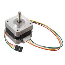
A bipolar stepper motor has one winding per stator phase. A two-phase bipolar stepper motor will have 4 leads. In a bipolar stepper, we don’t have a common lead like in a unipolar stepper motor. Hence, there is no natural reversal of the current direction through the winding. A bipolar stepper motor has an easy wiring arrangement but its operation is a little complex. In order to drive a bipolar stepper, we need a driver IC with an internal H bridge circuit. This is because, in order to reverse the polarity of stator poles, the current needs to be reversed. This can only be done through an H bridge.
ULN2003 Stepper driver
The ULN2003A contains seven Darlington transistor drivers and is somewhat like having seven TIP120 transistors all in one package.T he ULN2003A can pass up to 500 mA per channel and has an internal voltage drop of about 1V when on. It also contains internal clamp diodes to dissipate voltage spikes when driving inductive loads To control the stepper, apply the voltage to each of the coils in a specific sequence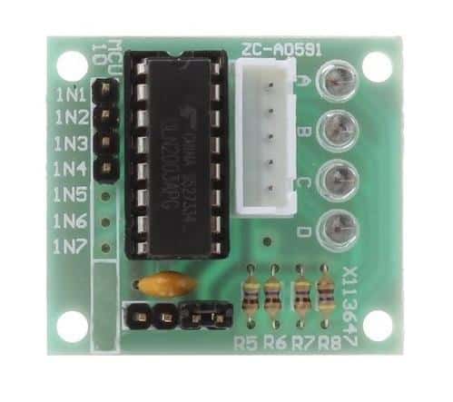
Circuit Diagram
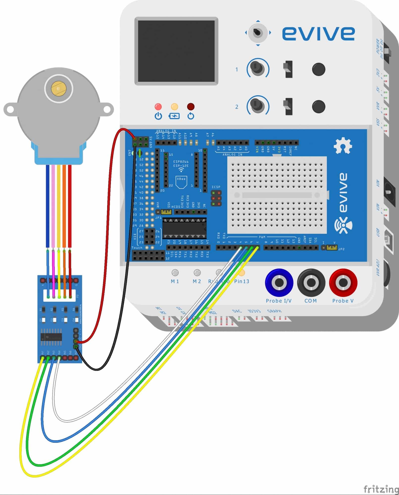
- Connect “28-BYJ48” stepper motor 5 wire female bus with “ULN2003” stepper motor driver male bus as shown in figure
- Connect pin having “ +” sign on “ULN2003” stepper motor driver to “VCC” of evive
- Connect pin having “-” sign on “ULN2003” stepper motor driver to “GND” of evive
- Connect “IN1” to digital pin number 7 of evive
- Connect “IN2” to digital pin number 6 of evive
- Connect “IN3” to digital pin number 5 of evive
- Connect “IN4” to digital pin number 4 of evive
Arduino Code
/*
 * evive
 *
 * this code demonstrate interfacing of 28-BYJ45 stepper motor
 *
 * Created on 13 june 2018
 * By punit chotaliya
 *
 */

// declaring signal pin for stepper motor
#define IN1  7
#define IN2  6
#define IN3  5
#define IN4  4

int Steps = 0;            //declaring variable for steps and initializing it with  value 0
boolean Direction = true;// declaring variable for Direction
unsigned long last_time;    // declaring variable for lst time
unsigned long current_time ;  // declaring variable for current time
int steps_left=4095;          // total number of steps required to complete one rotation is 4096  hence we hae initialized this ariable with value 4095
long time;               // declarin variable for storing time

void setup()
{

//  declaring signal pin for stepper motor as a output pins
pinMode(IN1, OUTPUT);
pinMode(IN2, OUTPUT);
pinMode(IN3, OUTPUT);
pinMode(IN4, OUTPUT);

}

void loop()
{
  // while steps_left are grater than 0 rotate stepper motor in that directio
  // and if not then rotate in oposite direction

  while(steps_left>0)
     {
        current_time = micros();          // save current time in currenttime variable using function "micros()"
        if(current_time-last_time>=1000) // check if there is difference of 1 second between last time and current time
            {
                stepper(1);                  //
                time=time+micros()-last_time;  // updating time variable with latest time
                last_time=micros();            // updating last time value
                steps_left--;                // decrement steps left by 1
            }
     }

     delay(250);

  Direction=!Direction;  // change the direction of motor
  steps_left=4095;      //   and reinitializing steps left with value 4095
}

void stepper(int value){
  for (int x=0;x<value;x++){
switch(Steps){
   case 0:
     digitalWrite(IN1, LOW);
     digitalWrite(IN2, LOW);
     digitalWrite(IN3, LOW);
     digitalWrite(IN4, HIGH);
   break;
   case 1:
     digitalWrite(IN1, LOW);
     digitalWrite(IN2, LOW);
     digitalWrite(IN3, HIGH);
     digitalWrite(IN4, HIGH);
   break;
   case 2:
     digitalWrite(IN1, LOW);
     digitalWrite(IN2, LOW);
     digitalWrite(IN3, HIGH);
     digitalWrite(IN4, LOW);
   break;
   case 3:
     digitalWrite(IN1, LOW);
     digitalWrite(IN2, HIGH);
     digitalWrite(IN3, HIGH);
     digitalWrite(IN4, LOW);
   break;
   case 4:
     digitalWrite(IN1, LOW);
     digitalWrite(IN2, HIGH);
     digitalWrite(IN3, LOW);
     digitalWrite(IN4, LOW);
   break;
   case 5:
     digitalWrite(IN1, HIGH);
     digitalWrite(IN2, HIGH);
     digitalWrite(IN3, LOW);
     digitalWrite(IN4, LOW);
   break;
     case 6:
     digitalWrite(IN1, HIGH);
     digitalWrite(IN2, LOW);
     digitalWrite(IN3, LOW);
     digitalWrite(IN4, LOW);
   break;
   case 7:
     digitalWrite(IN1, HIGH);
     digitalWrite(IN2, LOW);
     digitalWrite(IN3, LOW);
     digitalWrite(IN4, HIGH);
   break;
   default:
     digitalWrite(IN1, LOW);
     digitalWrite(IN2, LOW);
     digitalWrite(IN3, LOW);
     digitalWrite(IN4, LOW);
   break;
}
getDirection();
}
}

// declaring function for setting direction of stepper motor
void getDirection()
{
   if(Direction==1)
     {
       Steps++;
     }
  if(Direction==0)
     {
       Steps--;
     }
  if(Steps>7)
     {
       Steps=0;
     }
  if(Steps<0)
     {
       Steps=7;
     }
}
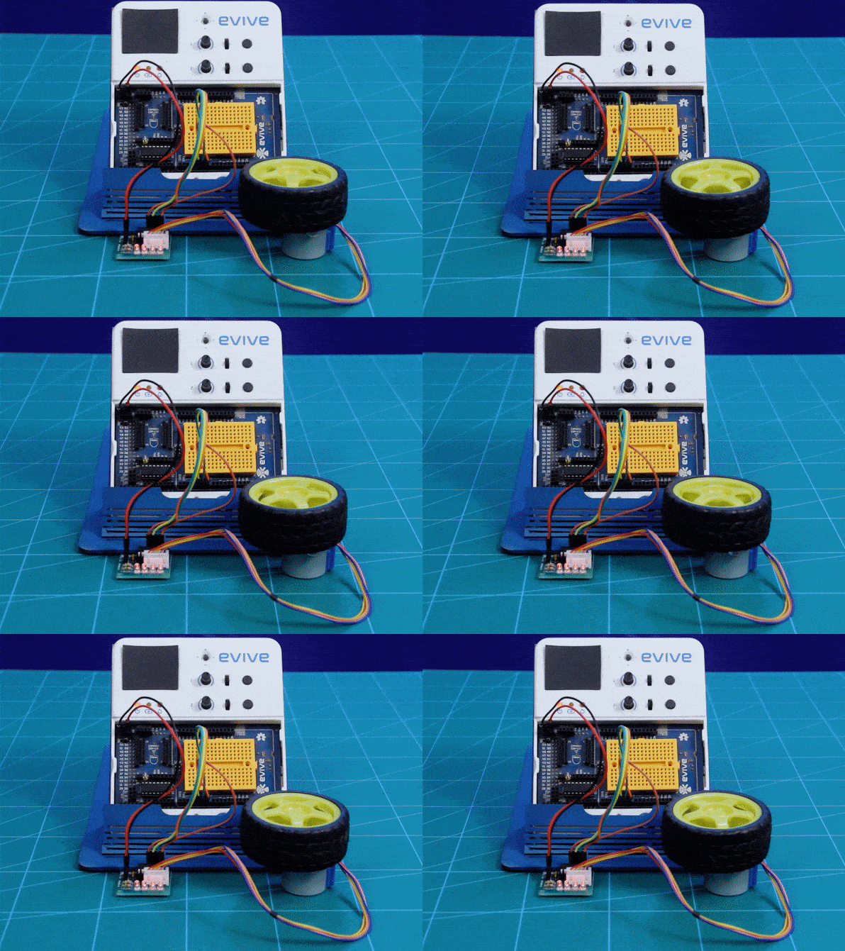
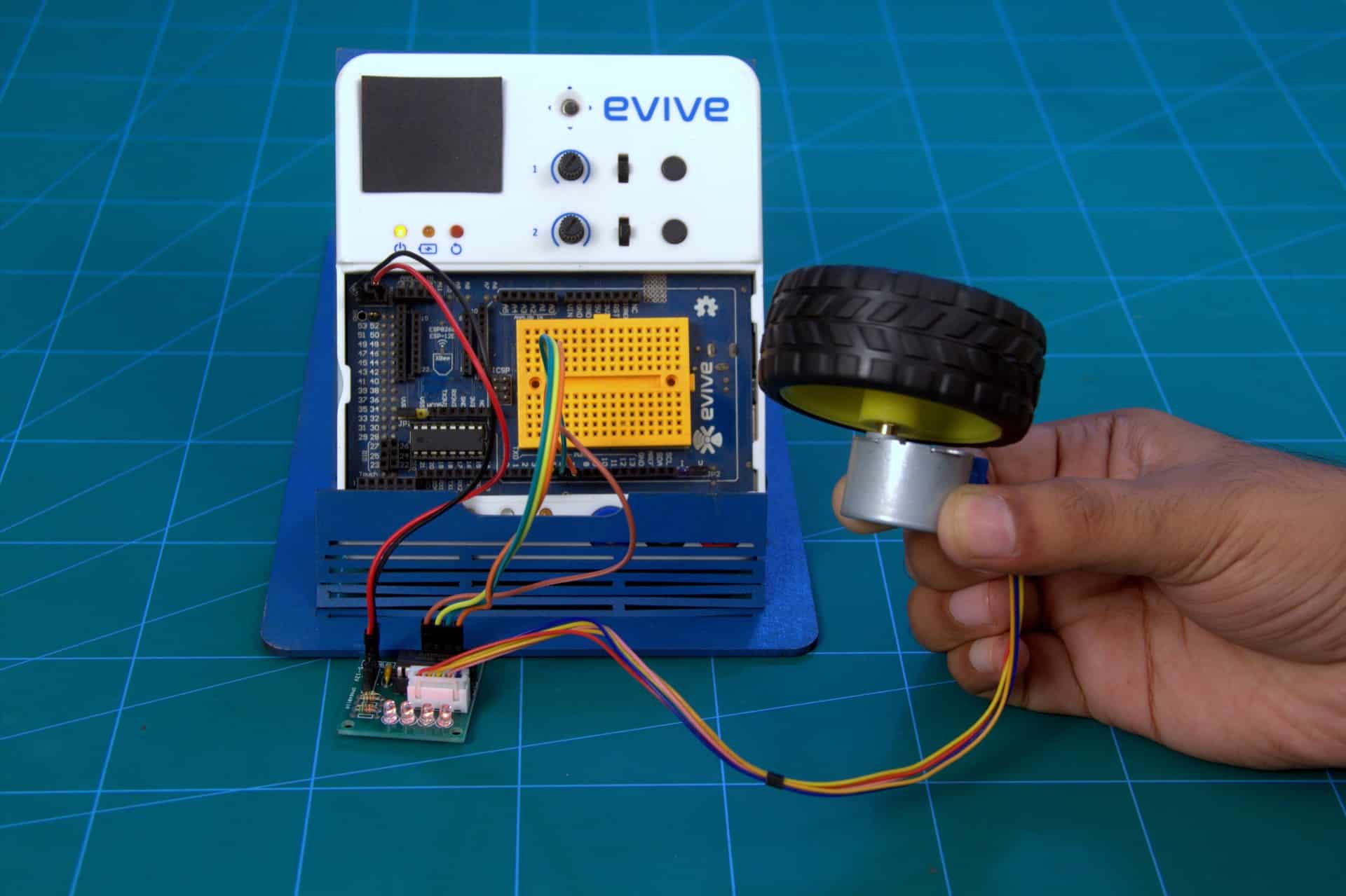
Expected Result
Conclusion
In this tutorial, we have discussed different types of stepper motors and their working. We also discussed the ULN2003 Stepper Driver and its role in controlling the stepper motors. Finally, we have seen an example of controlling a Unipolar Stepper Motor using Arduino and Evive. By following the steps given in this tutorial, you can easily control a stepper motor and make it perform desired operations.

