Introduction
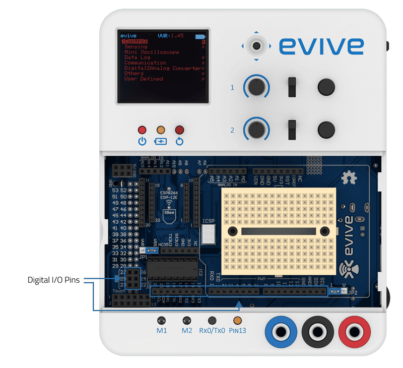
There are 28 digital I/O pins under evive’s magic lid, where digital I/O stands for digital input and output. These 28 pins can take a digital signal as an input and also give a digital signal as an output. A digital pin on evive can have either of the three states: HIGH, LOW, or FLOATING(this means logic 1,0 or either in terms of binary) and it remains in either one of them when it is used as input or as output. Now how to decide what is a state of a digital pin?
The state of the digital pin is determined by the fact that how much voltage it gives when it is used as an output pin or how much voltage is applied to it when it is used as an input pin. As evive is made on Arduino Mega hence it works on the logic level of 5v. This means that the states will be considered as follows:
| State | Description |
|---|---|
| 0 or LOW | When output or input at digital pin is in voltage range of 0V to 1.5V. |
| 1 or HIGH | When output or input at digital pin is in voltage range of 3.3V to 5V. |
| Floating | When the input to a digital pin is in voltage range of 1.5V to 3.3V its logic level can't be determined definitely. evive can randomly consider it as 1 or 0. Means if the state of the pin is read on evive then it fill be 1 sometimes and sometimes it will 0. |
Light-Emitting Diodes (LEDs)
An LED is a small device that glows when electricity passes through it. They are like tiny light bulbs but use less energy as compared to conventional filament bulbs. They’re also more energy efficient. so they don’t tend to get hot. LED bulbs and tube lights have picked up the front stage because they use less energy as compared to conventional filament bulbs.
Some concepts to keep in mind
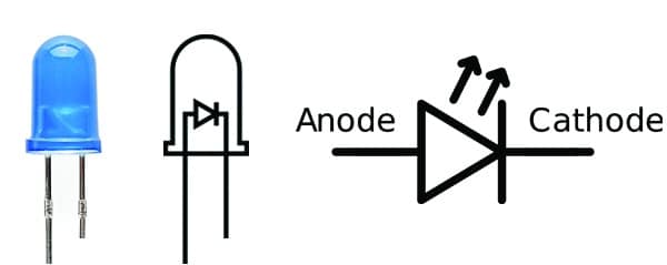
- Polarity Matters: Polarity is the property of having two poles that have opposite physical properties. In electronics, the two poles are: positive and negative. It decides the direction in which the charge in the wire/circuit will move. It indicates whether a circuit component is symmetric or not. LEDs allow current to flow only in one direction. Connecting them in reverse might blow them up. The positive side of the LED is the anode; it is generally the longer leg of the LED. The other, negative side of the LED is the cathode. The current always flows from the anode to the cathode. A reversed LED can keep an entire circuit from operating properly by blocking current flow.
- More current equals more light: The brightness of an LED is directly proportional to how much current it draws. That means two things: first, super bright LEDs drain batteries more quickly, because the extra brightness comes from the extra power being used; second, you can control the brightness of an LED by controlling the amount of current through it.
- …but too much current means ‘Boom!’: If you connect an LED directly to a current source it will try to use up as much power as it’s allowed to draw, and in the process, it might destroy itself. That’s why it’s important to limit the amount of current flowing across the LED. Resistors are used in circuits for this purpose to protect the LED from blowing itself up by drawing too much current.
evive has an LED (named Pin 13) whose positive terminal is connected internally to digital pin 13 and the negative terminal is connected to GND i.e. ground. A resistor is present between the digital pin 13 and the positive terminal of the LED to prevent excess current from flowing through the LED. When digital pin 13 is HIGH, the current passes through the LED and it glows; when it is LOW, no current passes through the LED. Hence, it does not glow.
Configuring a Digital Pin as an Output Pin
In order to declare a digital pin as an output in evive that pin should be configured as OUTPUT using the pinMode function available on Arduino IDE. This can be done using the following statement:
pinMode(pin, OUTPUT);
where the pin is the digital pin number you want to initialize as output.


Using the digitalWrite() function in Arduino IDE, you can set a digital pin either to a HIGH or LOW value.
Example: Making an LED Blink
In this Arduino IDE sketch, we will turn ON the LED for 1 second, then turn it OFF for another 1 second and repeat, i.e. make it blink.
Below is the sketch:
/*
 Blink
 Turns on an LED on for one second, then off for one second, repeatedly.
 Explore more on : https://thestempedia.com/tutorials/evive-digital-output/
*/

int LEDPin = 13;

void setup() {
 // initialize digital pin LEDPin as an output.
 pinMode(LEDPin, OUTPUT);
}

void loop() {
 digitalWrite(LEDPin, HIGH); // turn the LED on (HIGH is the voltage level)
 delay(1000); // wait for a second
 digitalWrite(LEDPin, LOW); // turn the LED off by making the voltage LOW
 delay(1000); // wait for a second
}
Conclusion
In this lesson, we have learned about the 28 digital I/O pins of evive, the different states of a digital pin, LEDs, and the concept of polarity, current, and resistors. We also learned how to configure a digital pin as an output and how to use the digitalWrite function to control the state of an LED. Understanding the principles behind digital I/O pins and LEDs is essential for programming and controlling circuits.