Introduction
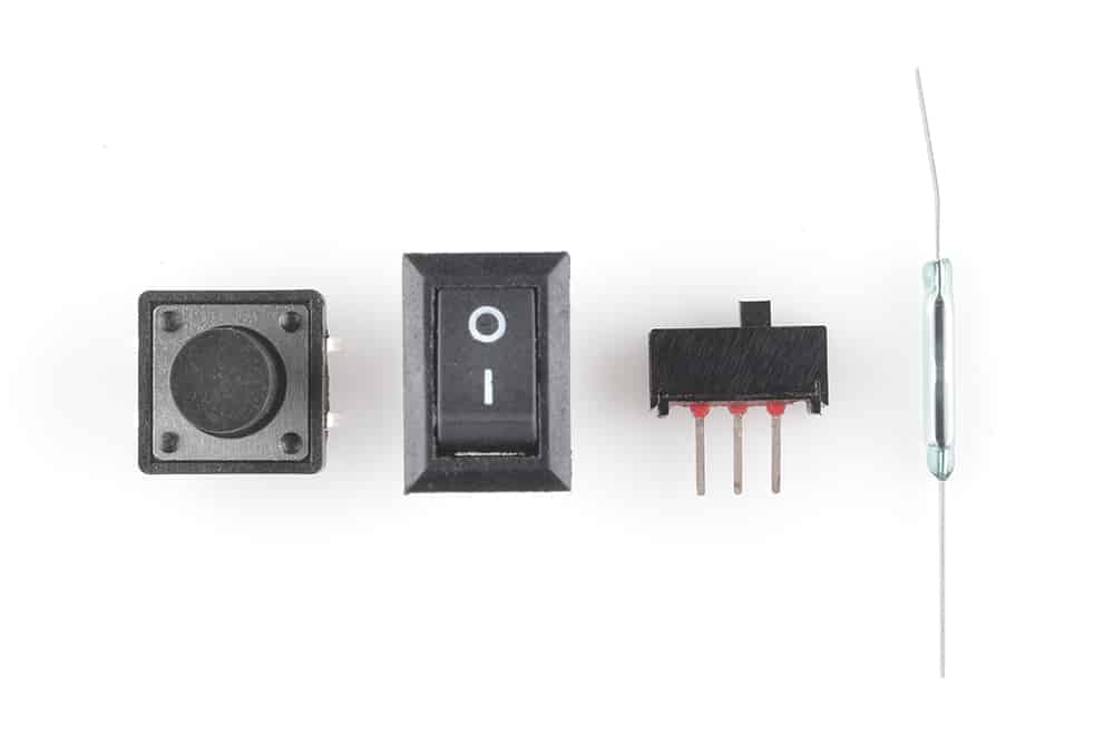
A switch is one of the most basic, but very important components in a circuit. When the switch is open, the circuit is broken, and no current will flow through it. When the switch is closed, the circuit is closed or made, and therefore, current will flow through it.
Switches can broadly be classified into two types:
- Mechanical Switches
- Electrical Switches
Mechanical switches can further be classified into two types:
- Maintained Switches: These switches stay in one state i.e. either ON or OFF, unless the state is changed by someone. E.g. wall switches. Once you press them, they remain in the same state, i.e. ON till the time you manually change it.
- Momentary switches: These switches stay in a state i.e. either ON or OFF, as long as they are activated. They come back to their original state once the are released. E.g. keys on a keyboard. They remain active only till the time they are pressed. As soon as you stop pressing them, they go back to their original state, i.e. OFF state.
Interfacing switch with evive
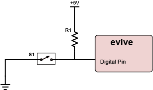
Imagine that evive has only one digital pin configured as an input. A code tries to read the state of the pin, while nothing is connected to it. It will be difficult to tell whether the state is HIGH or LOW. This phenomenon is known as floating. To prevent this situation of an unknown state, either a pull-up or a pull-down resistor is connected to ensure that the pin is always either in either a HIGH or LOW state while using only a small amount of current. A pull-up or pull-down resistor is always used with switches.
With a pull-up resistor, the input pin reads a HIGH state when the switch is not pressed because the resistor is connected to the supply (+5V in this case) and as a result a small current flows from the supply to the input pin. When the switch is pressed, it connects the input pin directly to the ground. The current flows through the resistor to the ground, bypassing the input pin; thus, the input pin reads a LOW state.
When a pull-down resistor is used, the input pin reads a LOW state when the switch is not pressed. As soon as the switch is pressed, it connects the input pin directly to the supply. The current flows through the resistor to the ground, thus the input pin reads a high state.
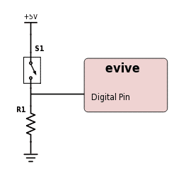
Generally, a 10kΩ is considered both a good pull-up and a pull-down resistor.
Example: Changing the state of Pin 13 LED using a tactile switch
In this example, we will change the state of the LED each time the tactile switch is pressed.
Case I: Pull-up Resistor
Circuit
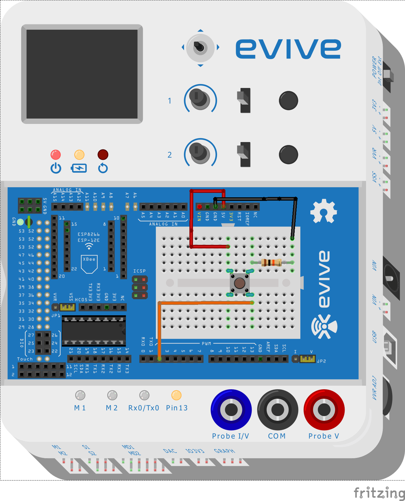
Follow the steps below to make the circuit:
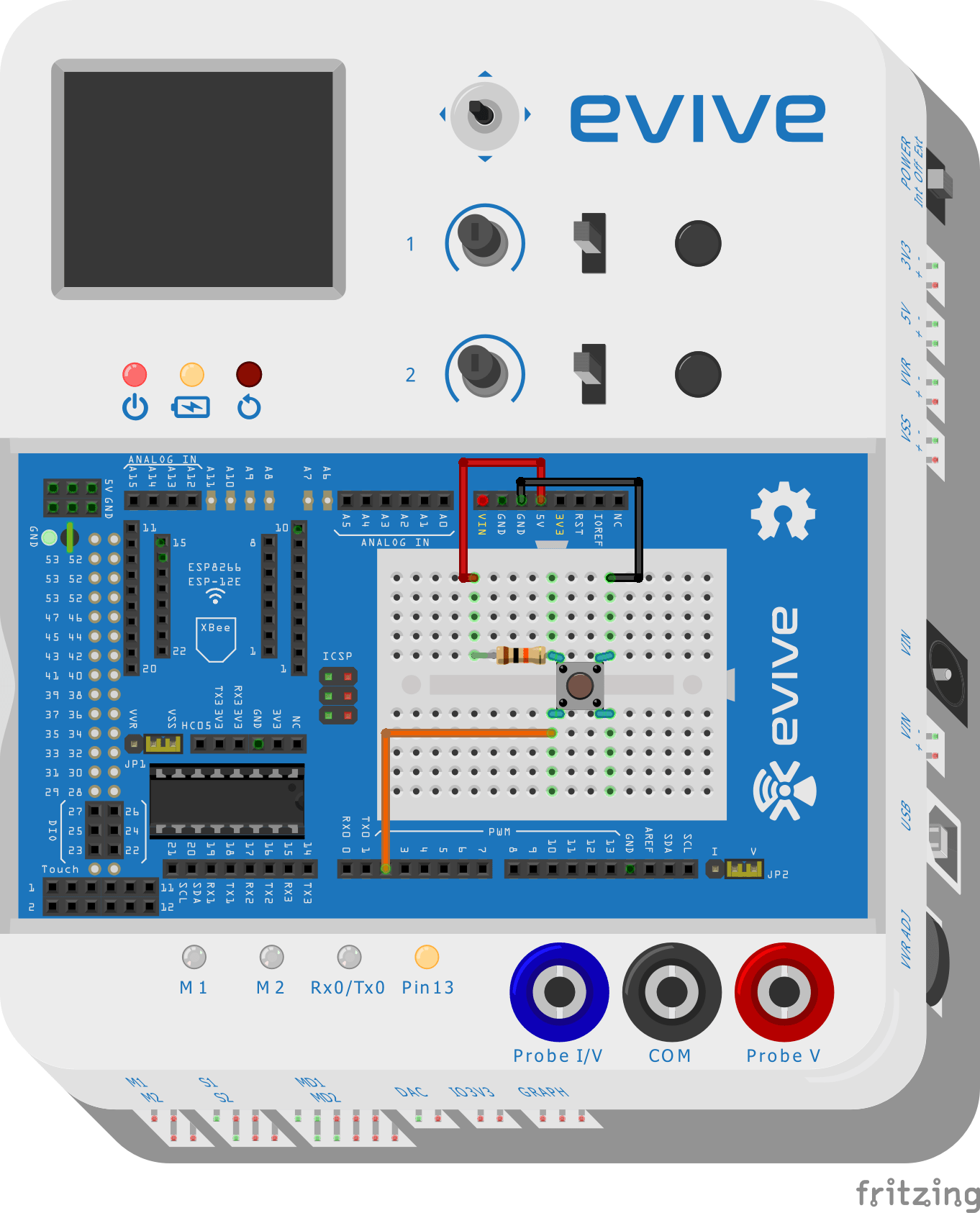
- Take a red male-to-male jumper wire and connect one of its ends to the 5V supply pin above the breadboard, as shown in the circuit diagram. Take the other end and insert it in the 5th hole from the left of the first row of the breadboard.
- Take a black male-to-male jumper wire and connect one of its ends to the GND pin above the breadboard, as shown in the circuit diagram. Take the other end and insert it in the 6th hole from the right of the first of the breadboard.
- Take the tactile switch/push button and insert it across the dip in the breadboard such that it top-right leg is in the same column as that of the black male-to-male jumper wire.
- Take the 10kΩ resistor and insert one of its legs in the same column as that of the top-left leg of the tactile switch, exactly above it, as shown in the circuit diagram. Insert the other leg in the same column as that of the red jumper wire.
- Take an orange male-to-male jumper wire and insert one of its ends in the same column as that of the bottom-left leg of the tactile switch, as shown in the circuit diagram. Take the other end and connect it to digital pin 2, below the breadboard, as shown.
Below is the complete circuit diagram:
Flow Chart
Below is the flow chart:

Arduino IDE Sketch
Below is the Arduino IDE Sketch:
int SwitchPin = 2;
int LEDPin = 13;
boolean State = false;

void setup() {
 // put your setup code here, to run once:
 pinMode(SwitchPin, INPUT);
 pinMode(LEDPin, OUTPUT);
}

void loop() {
 // put your main code here, to run repeatedly:
 if(!digitalRead(SwitchPin))
 {
 if(State == true)
 {
 State = false;
 }
 else
 {
 State = true;
 }
 digitalWrite(LEDPin, State);
 delay(500);
 }
}
Case II: Pull-down Resistor
Circuit
Follow the steps below to make the circuit:
- Take a red male-to-male jumper wire and connect one of its ends to the 5V supply pin above the breadboard, as shown in the circuit diagram. Take the other end and insert it in the 9th hole from the left of the second row of the breadboard.
- Take a black male-to-male jumper wire and connect one of its ends to the GND pin above the breadboard, as shown in the circuit diagram. Take the other end and insert it in the 1st hole from the right of the first of the breadboard.
- Take the tactile switch/push button and insert it across the dip in the breadboard such that it top-left leg is in the same column as that of the red male-to-male jumper wire.
- Take the 10kΩ resistor and insert one of its legs in the same column as that of the top-right leg of the tactile switch, exactly above it, as shown in the circuit diagram. Insert the other leg in the same column as that of the black jumper wire.
- Take an orange male-to-male jumper wire and insert one of its ends in the same column as that of the bottom-right leg of the tactile switch, as shown in the circuit diagram. Take the other end and connect it to digital pin 2, below the breadboard, as shown.
Below is the complete circuit diagram:
Flow Chart
Below is the flow chart: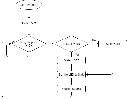
Arduino IDE Sketch
Below is the Arduino IDE Sketch:
int SwitchPin = 2;
int LEDPin = 13;
boolean State = false;

void setup() {
 // put your setup code here, to run once:
 pinMode(SwitchPin, INPUT);
 pinMode(LEDPin, OUTPUT);
}

void loop() {
 // put your main code here, to run repeatedly:
 if(digitalRead(SwitchPin))
 {
 if(State == true)
 {
 State = false;
 }
 else
 {
 State = true;
 }
 digitalWrite(LEDPin, State);
 delay(500);
 }
}
Conclusion
In conclusion, switches are a very important component in a circuit and can be classified into mechanical and electrical switches. Pull–up and pull–down resistors are used to prevent the phenomenon of floating, and in this lesson, we have gone through the steps to interface a tactile switch with evive and change the state of Pin 13 LED using a tactile switch, with both pull–up and pull–down resistors.