Introduction
In programming, an interrupt is a signal that hardware or software sends to the processor alerting it of an event that needs immediate attention. An interrupt alerts the processor to a high-priority condition requiring the interruption of the current code the processor is executing. The processor responds by stopping all of its current activities, saving its state, and executing a function called an interrupt handler (or an interrupt service routine, ISR) to deal with the event. This interruption is temporary, and, after the interrupt handler finishes, the processor resumes its normal activities.
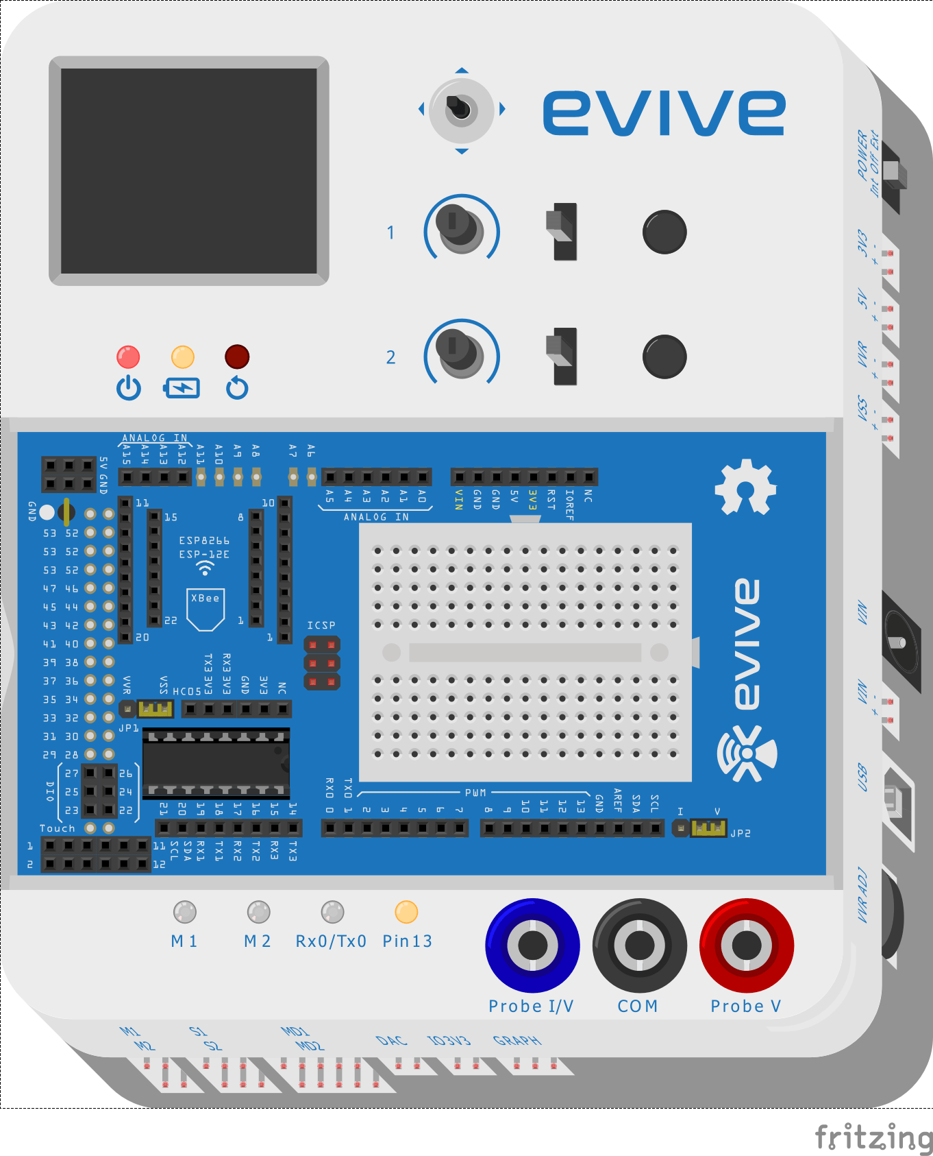
evive has 6 external interrupt pins:
- 2 (interrupt 0)
- 3 (interrupt 1)
- 18 (interrupt 5)
- 19 (interrupt 4)
- 20 (interrupt 3)
- 21 (interrupt 2)
These pins can be configured to trigger an interrupt on a LOW level, a rising or falling edge of a PWM signal, or a change in level.
attachInterrupt()
In the Arduino IDE environment, you can attach interrupts using the attachInterrupt() function. There are two different approaches with which you can initialize an interrupt pin:
attachInterrupt(digitalPinToInterrupt(pin), ISR, mode);
AND
attachInterrupt(interrupt, ISR, mode);
where
- an interrupt is the number of the interrupt pin (from 0-5)
- the pin is the pin number
- ISR is the function that you call when an interrupt occurs (this function does not take parameters, and returns nothing. This function is also called an interrupt service routine)
- the mode defines how the interrupt occurs.
There exist several modes, as shown in the table below:
| Trigger Type | Trigger Action |
|---|---|
| LOW | Trigger the interrupt whenever the pin is low |
| CHANGE | Trigger the interrupt whenever the pin value changes |
| RISING | Trigger when the pin goes from low to high |
| FALLING | Trigger when the pin goes from high to low |
detachInterrupt()
When we don’t need any kind of interrupt we can stop it, or override it by using the detachInterrupt() function. There are two ways to use it:
detachInterrupt(interrupt);
AND
detachInterrupt(digitalPinToInterrupt(pin));
Example
This example demonstrates the use of interrupts in evive. For this, you must connect digital pins 2 and 7 using a jumper wire. In this program, we will control the Pin 13 LED using evive’s push button 1, i.e. tactile switch 1, an interrupt pin.
Below is the Arduino IDE sketch:
/*
This program demonstrates the use of interrupts with evive.
You have to connect digital pins 2 and 7 using a jumper wire.
In this program we will control and LED (connected to pin 13)
using pushbutton 1 of evive and interrupt pin.
*/
#include <evive.h>
int interruptPin = 2; // Interrupt pin connected to pin 2
int OutPin = 7; // Interrupt signal is generated from digital pin 7

boolean state = false; // Variable to store the state of LED

void setup() {
// put your setup code here, to run once:
// Initalise all the pin
pinMode(LED_BUILTIN, OUTPUT);
pinMode(TACTILESW1, INPUT);
pinMode(OutPin, OUTPUT);
pinMode(interruptPin, INPUT_PULLUP);
// Initalise the interrupt pin
Serial.begin(9600);
attachInterrupt(digitalPinToInterrupt(interruptPin), changeState, CHANGE);
}

void loop() {
// put your main code here, to run repeatedly:
digitalWrite(LED_BUILTIN , state);
// Serial.println(digitalRead(PushPin));
digitalWrite(OutPin, digitalRead(TACTILESW1));
}

// Interrupt service routine function
void changeState(){
state = !state;
}
Conclusion
In this lesson, we have looked at how to use interrupts in evive. We discussed how interrupts can be initialized using the attachInterrupt() function in Arduino, and how to stop them using the detachInterrupt() function. We also looked at an example of how to use interrupts with evive to control the built-in LED using tactile switch 1. By understanding and utilizing the concepts of interrupts, the user can gain more control over their evive projects.


