
Introduction
In this project we will build a robotic car from scratch and control it using a smartphone (evive App) via Bluetooth.
Basics: What is Wheels?
Like real cars, the robotic car also have wheels which are actuated using DC motors. For a moving object to be stable, you need at least 3 contact points. Like, in car you have four wheels, but in bicycle, there are only two wheel. A cyclist can control bicycle only when he is cycling, but of he stops he can’t balance the cycle without resting his foot on the ground.
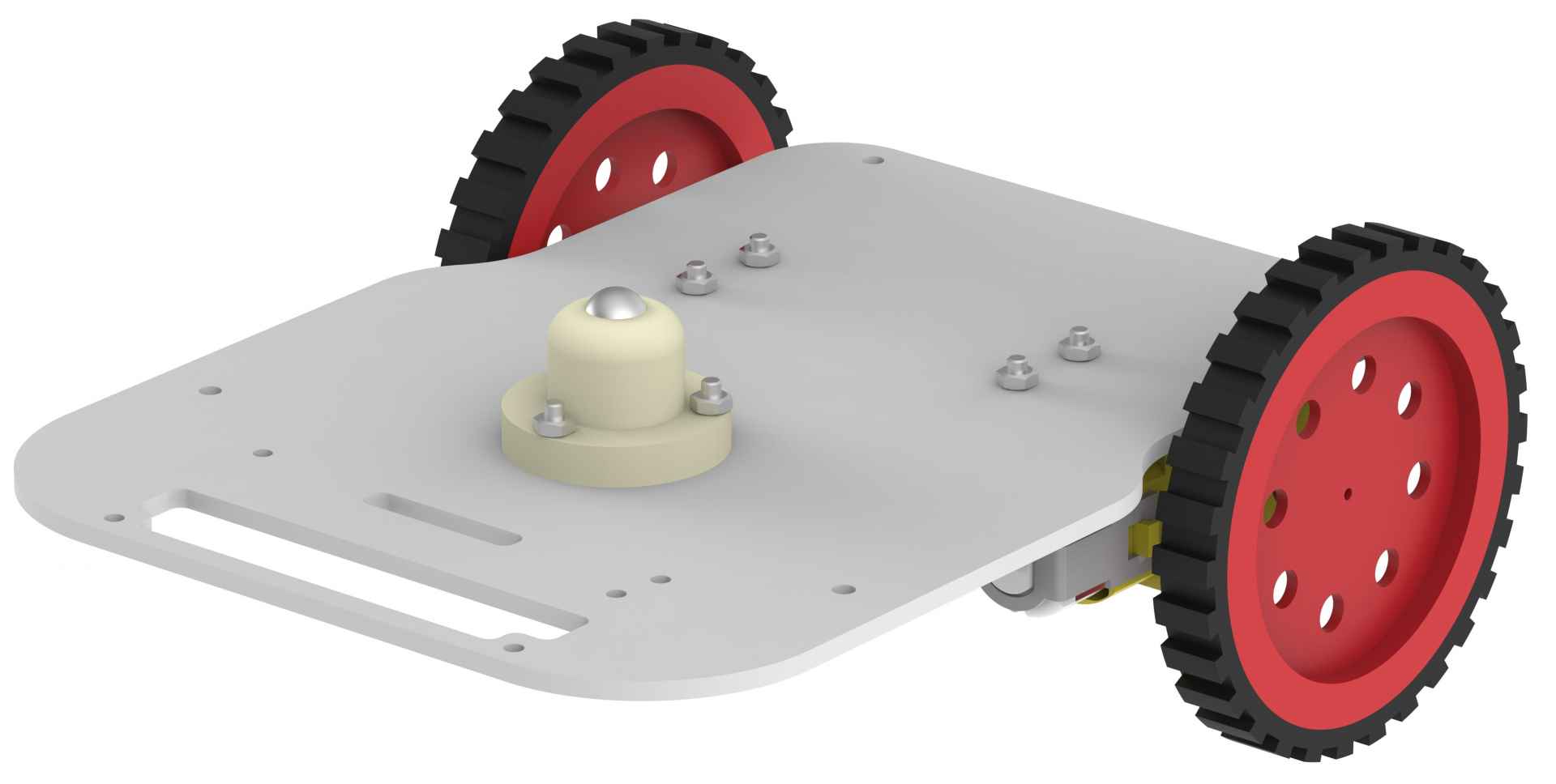
In our mobile robot, we have 2 wheels and one caster touching the ground. Caster wheel is just round ball rolling on the ground. It can move in any direction.
Differential Drive
A differential wheeled robot is a mobile robot whose movement is based on two separately driven wheels placed on either side of the robot body. It can thus change its direction by varying the relative rate of rotation of its wheels and hence does not require an additional steering motion.
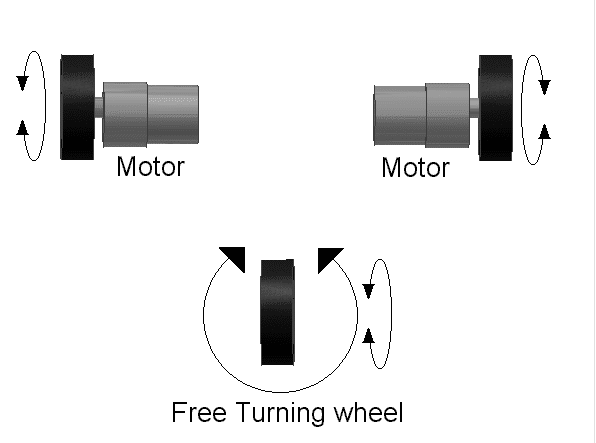
If both the wheels are driven in the same direction and speed, the robot will go in a straight line. If both wheels are turned with equal speed in opposite directions, the robot will rotate about the central point of the axis. Otherwise, depending on the speed of rotation and its direction, the center of rotation may fall anywhere on the line defined by the two contact points of the tires. While the robot is traveling in a straight line, the center of rotation is an infinite distance from the robot.
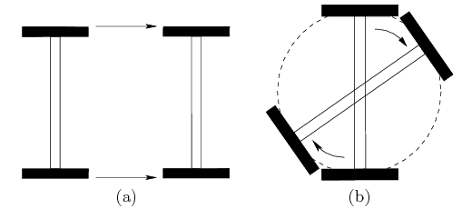
Figure: (a) Pure translation occurs when both wheels move at the same angular velocity; (b) pure rotation occurs when the wheels move at opposite velocities.
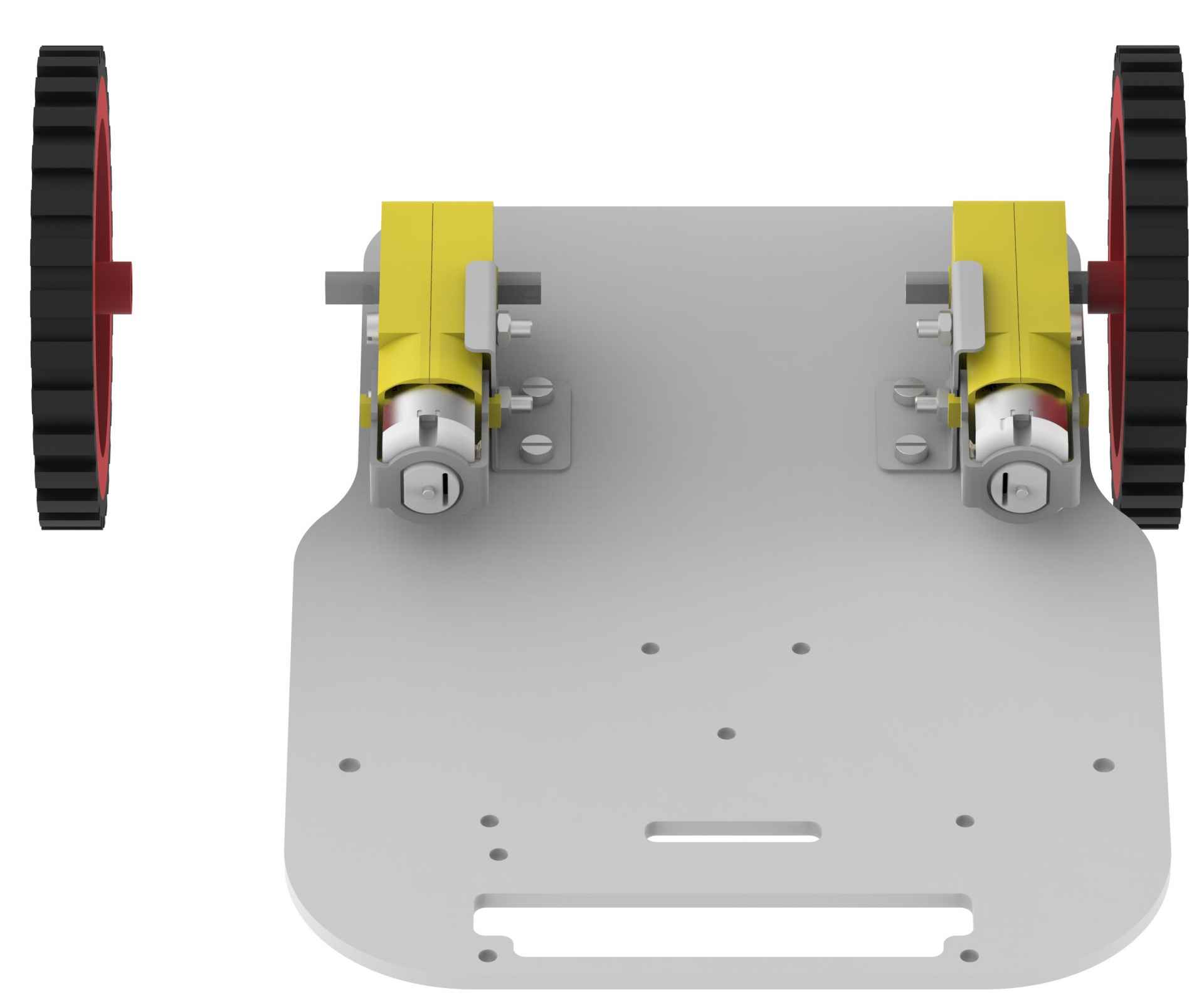
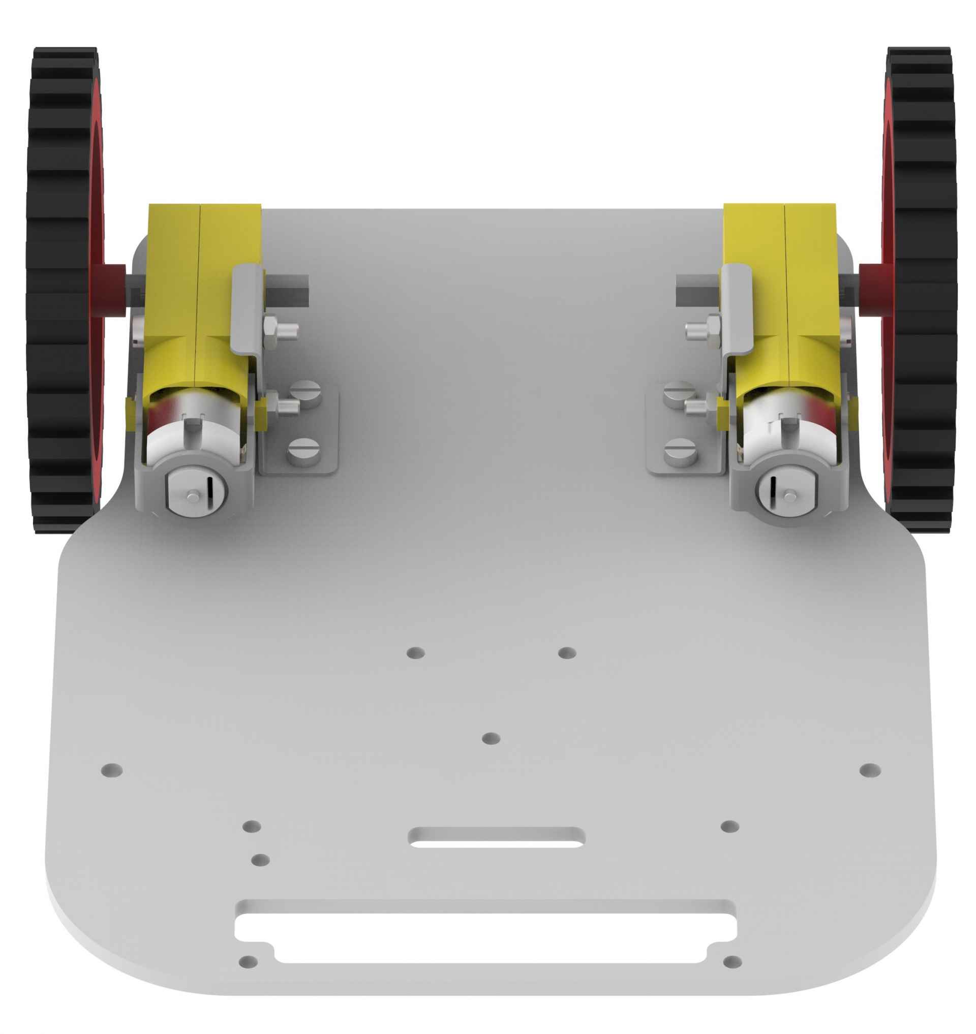
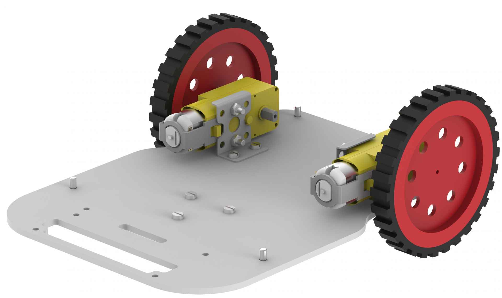
Assembly of the Robot
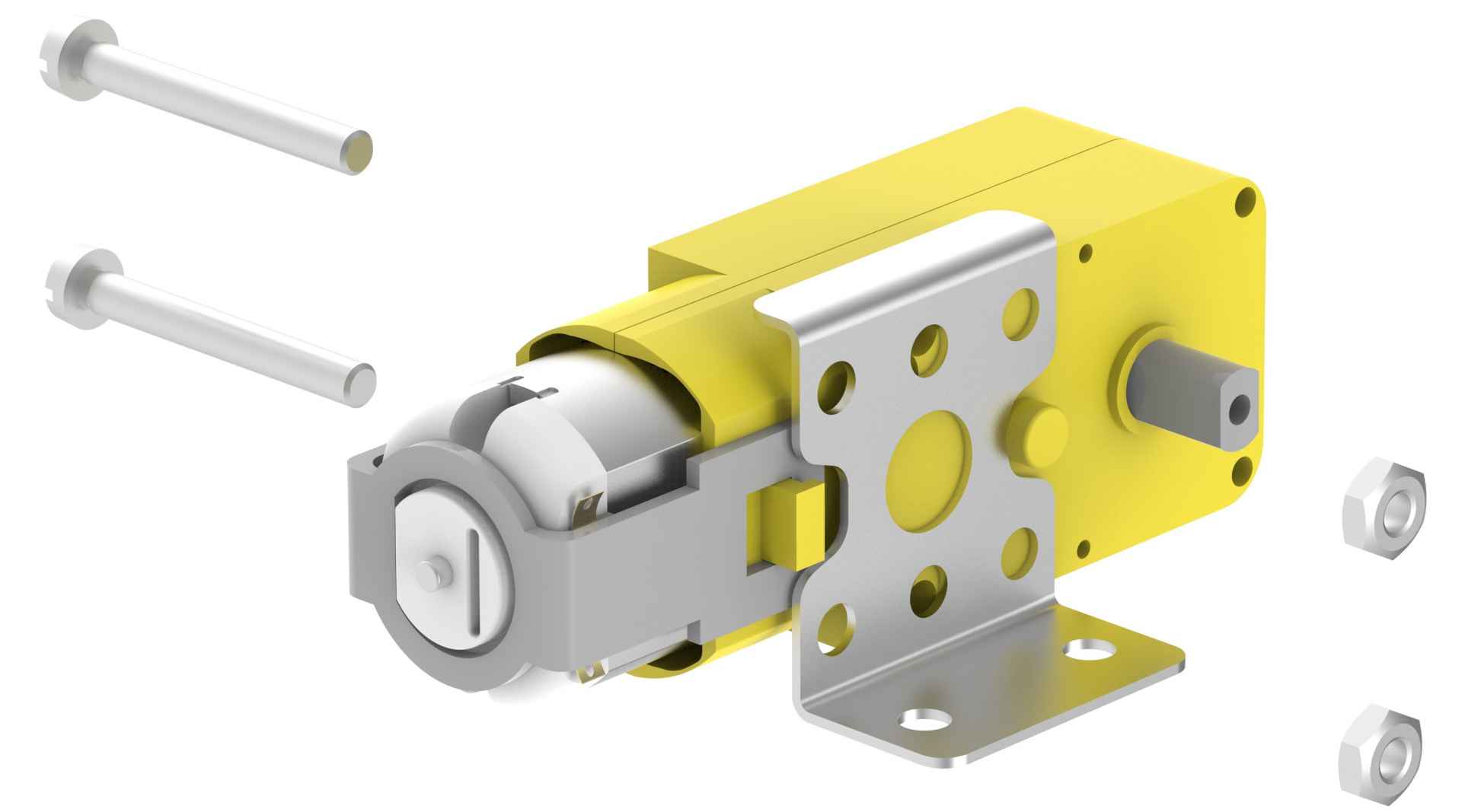
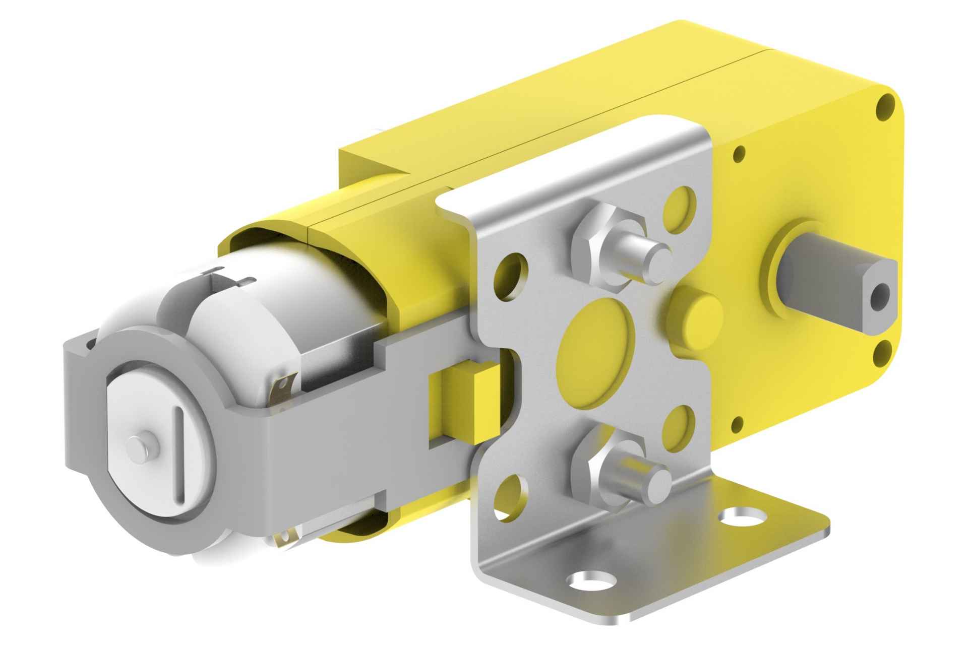
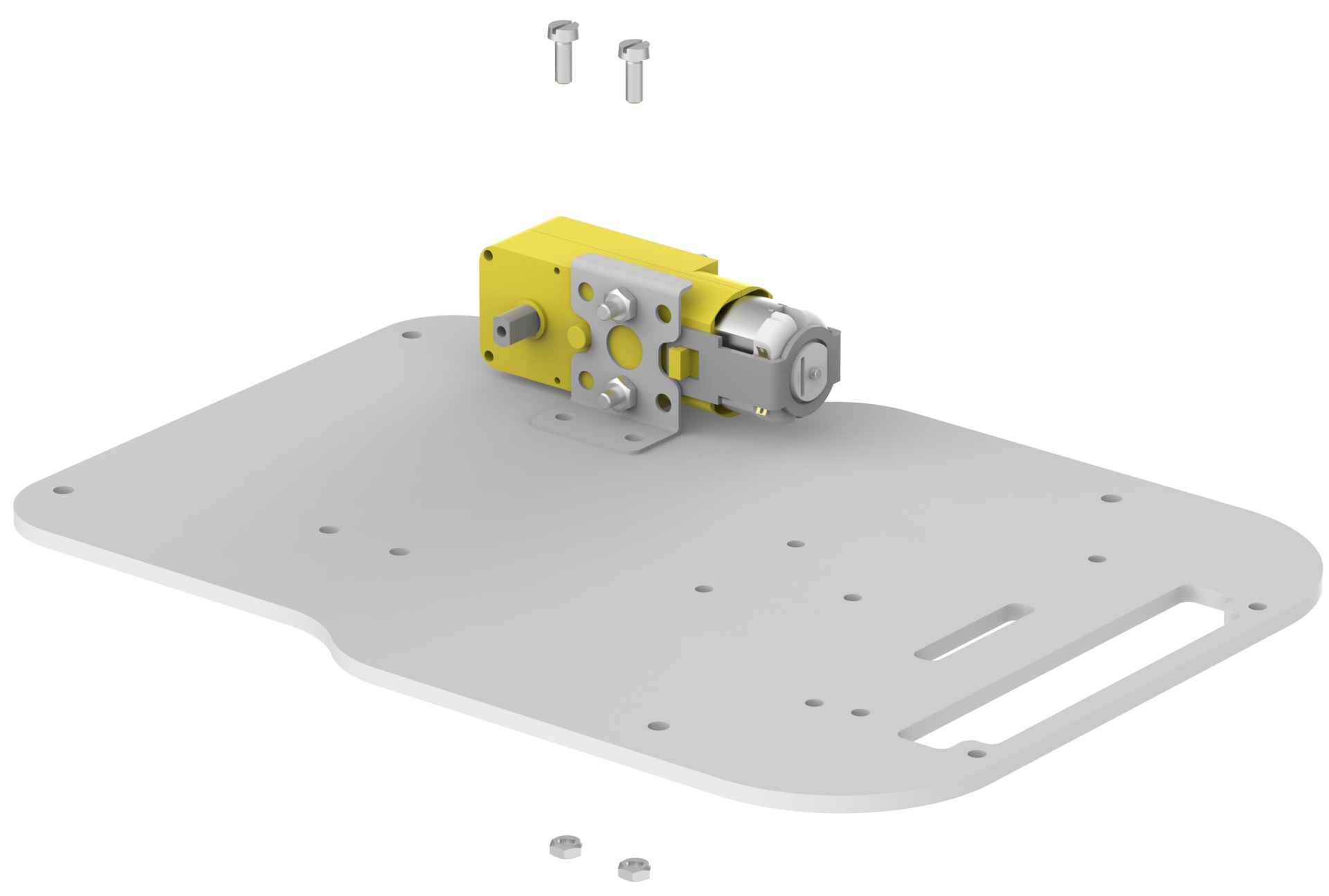
- Place an angle bracket on the motor as shown in the figure. Note that the racket should be placed on that side of a motor which has a circular extrusion coming out of the yellow body (white plastic body if you have a white motor). If you are preparing a right hand side motor, then your assembly should look like as shown in the figure, otherwise you have to mount the bracket in the upside-down position (for left motor).
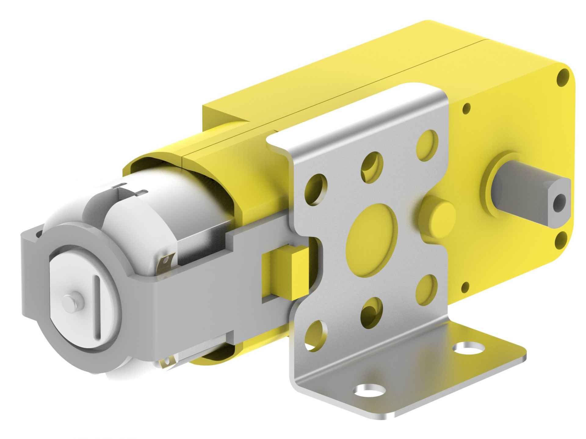
- Using two 12mm M3 bolts and two M3 nuts, fasten the motor and brackets.
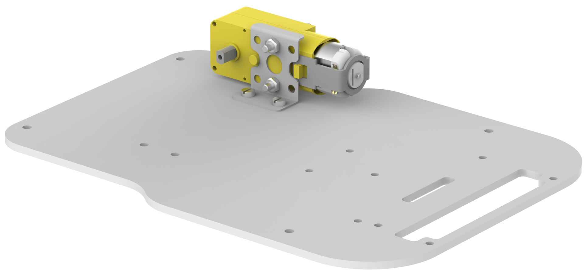
- Place the left motor bracket assembly on the lower base plate in the mounting holes provided.
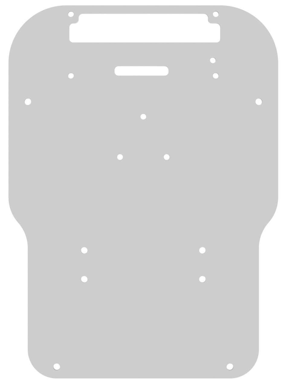
Note that, as the base plate is symmetric, you should keep in mind which motor is for right side and which one for left before mounting them.
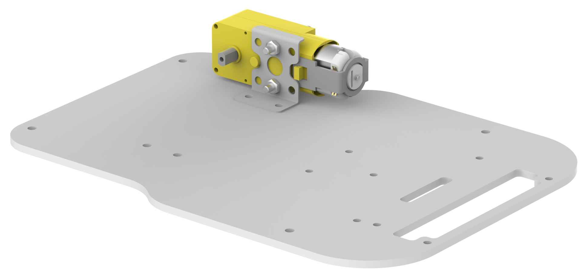
- Fasten the motor using two 8mm M3 bolts and two M3 nuts.
- Similarly mount the right motor using nuts and bolts. Ensure that you have mounted the motors in the exact way as shown in the figure.
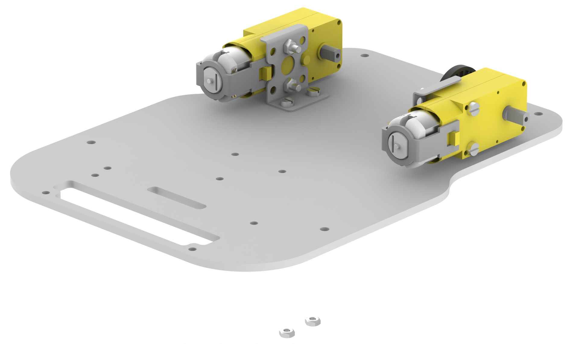
- Then, gently attach wheels on the motor shaft as shown in the figure.
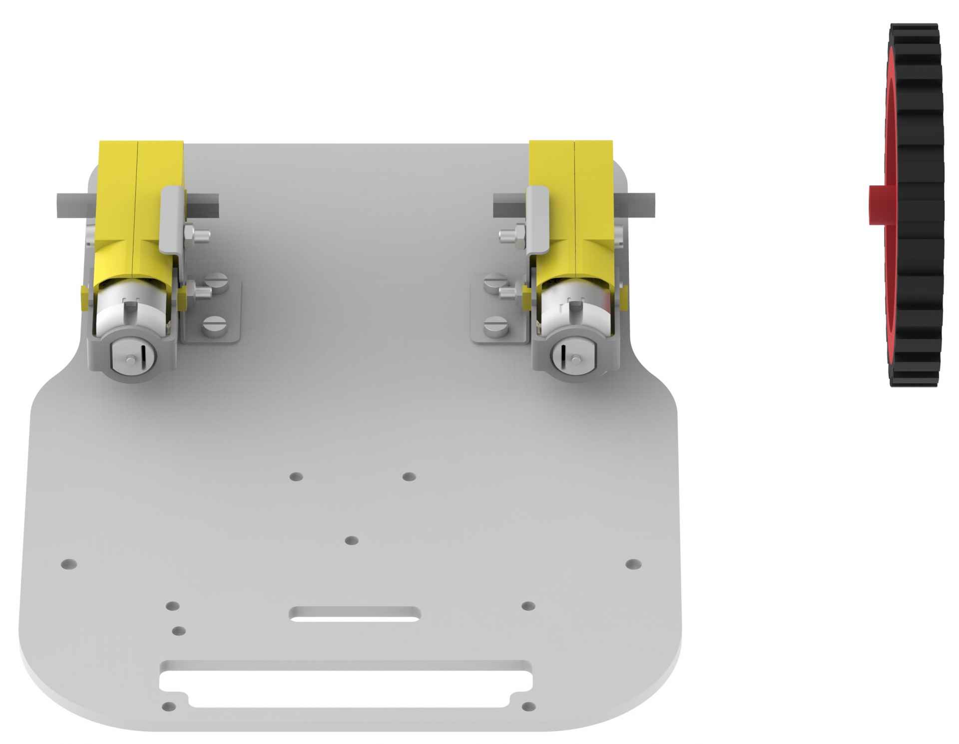
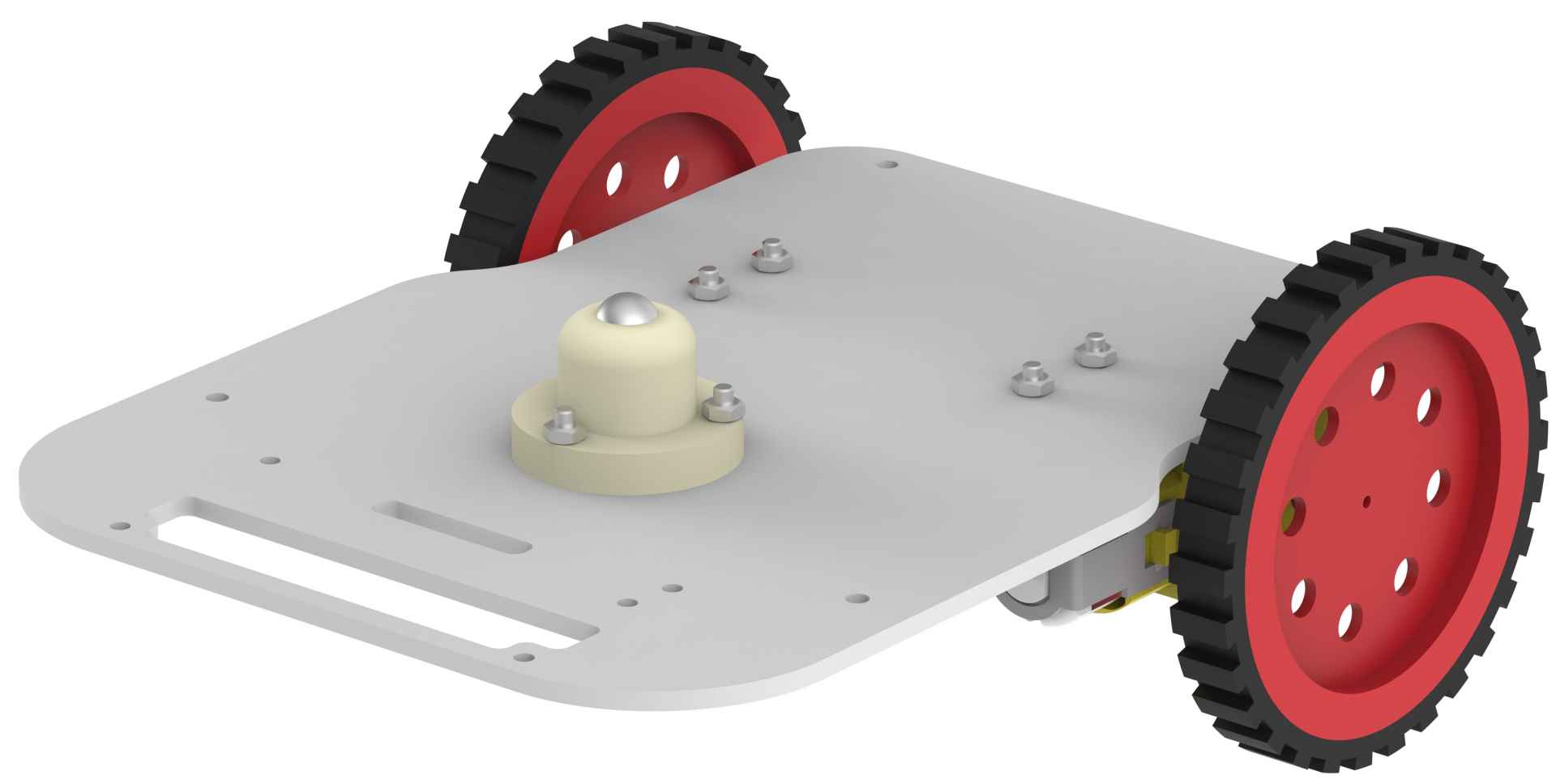
- Turn the lower base plate upside down and mount the castor wheel on the mounting holes provided on the base plate. Using three 12mm M3 bolts and three M3 nuts to fasten the castor wheel.
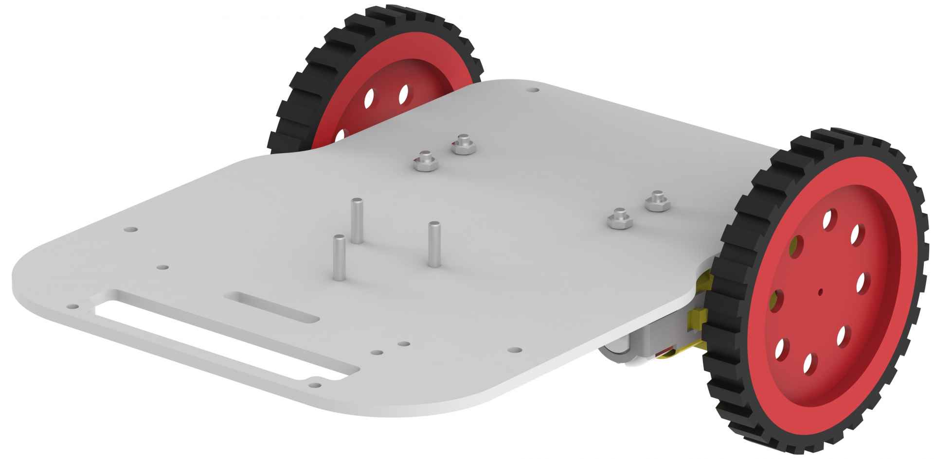
- Turn the lower base plate back to initial orientation.
- Now, using 8mm M3 bolts, mount four 40mm standoffs on the holes provided on the base plate.
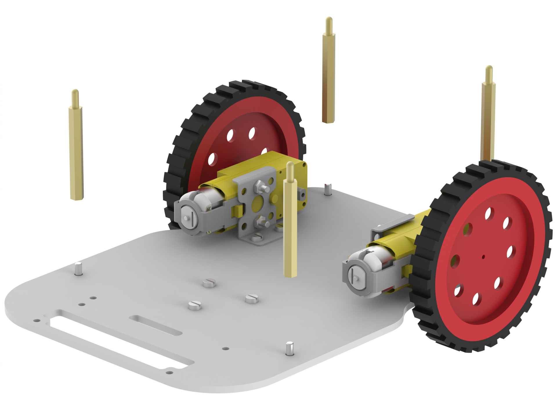
- Mount evive on upper base plate using two 12mm M3 bolts. Note that if you are not using encoders, then you can mount evive with all four bolts.
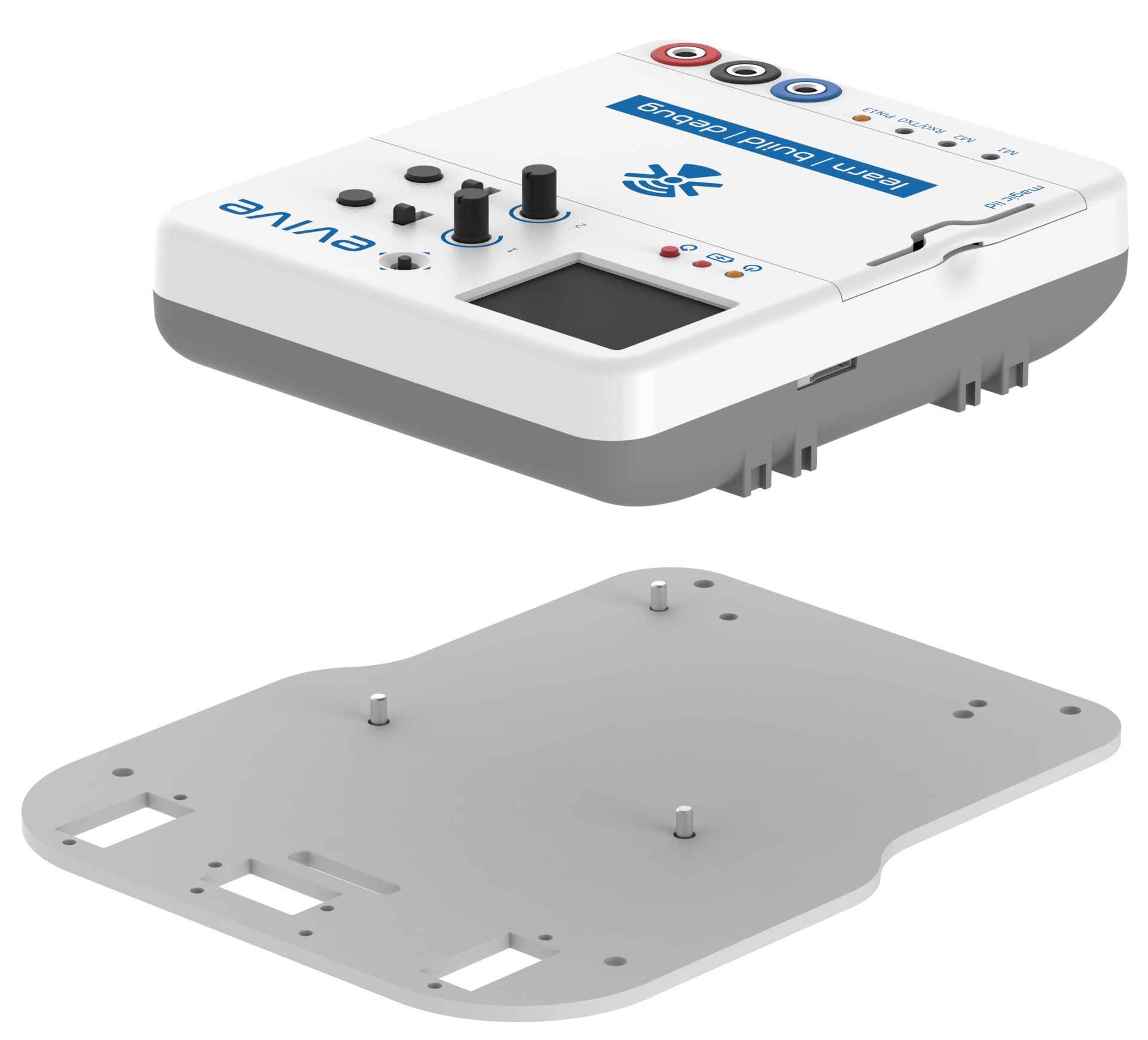
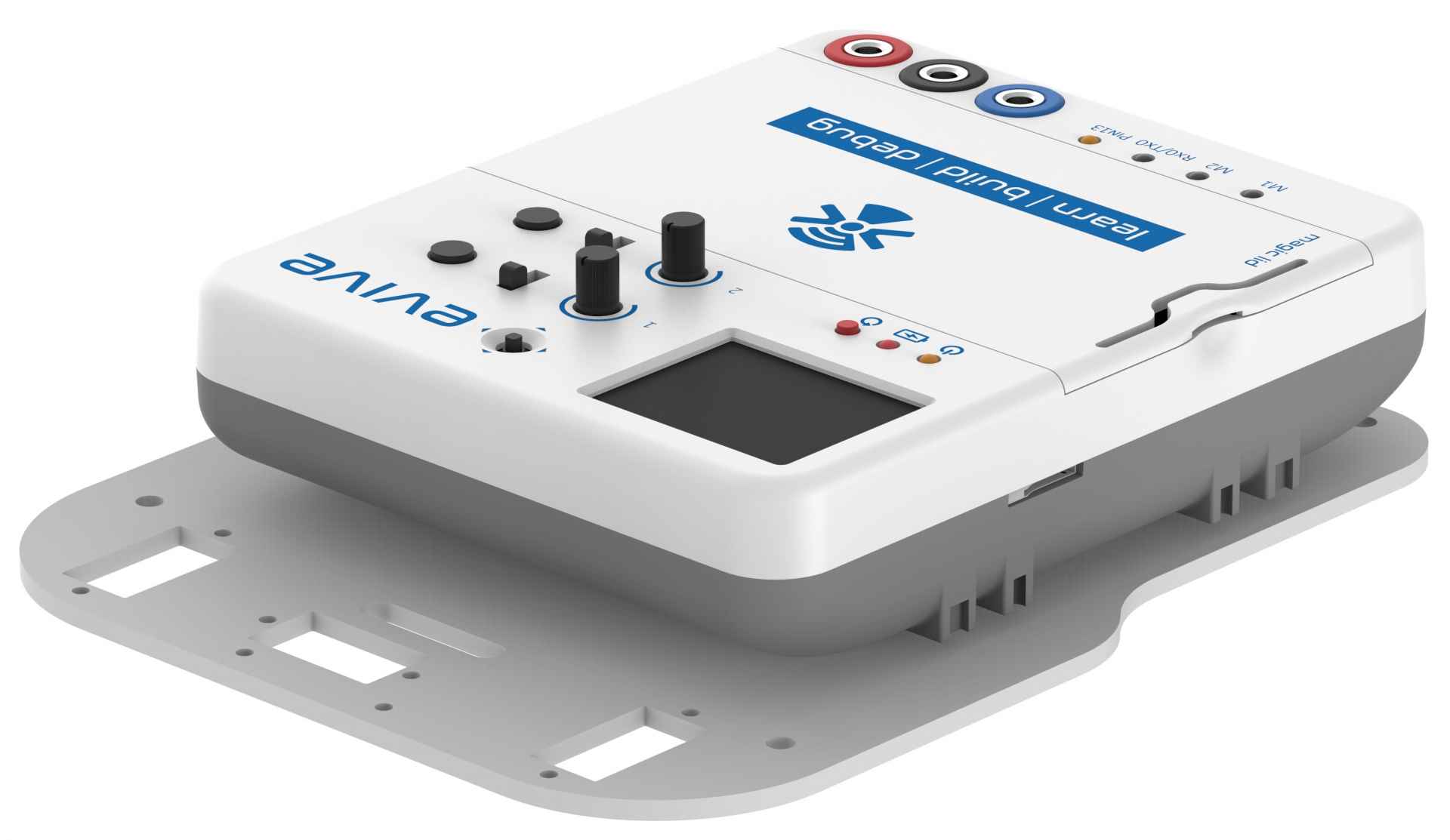
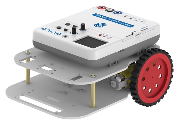
- Finally place the upper base plate on the standoffs of lower base plate.
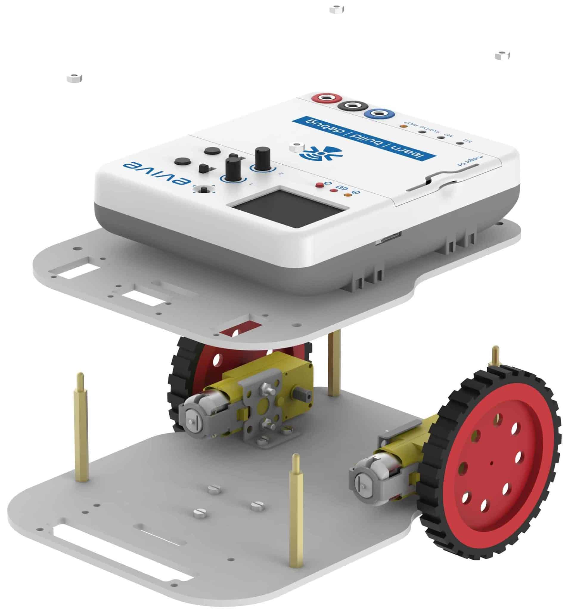
- If you want to increase the height at which the upper base plate is mounted, then you can do it, by attaching another 10mm standoffs on top of 40mm standoffs.
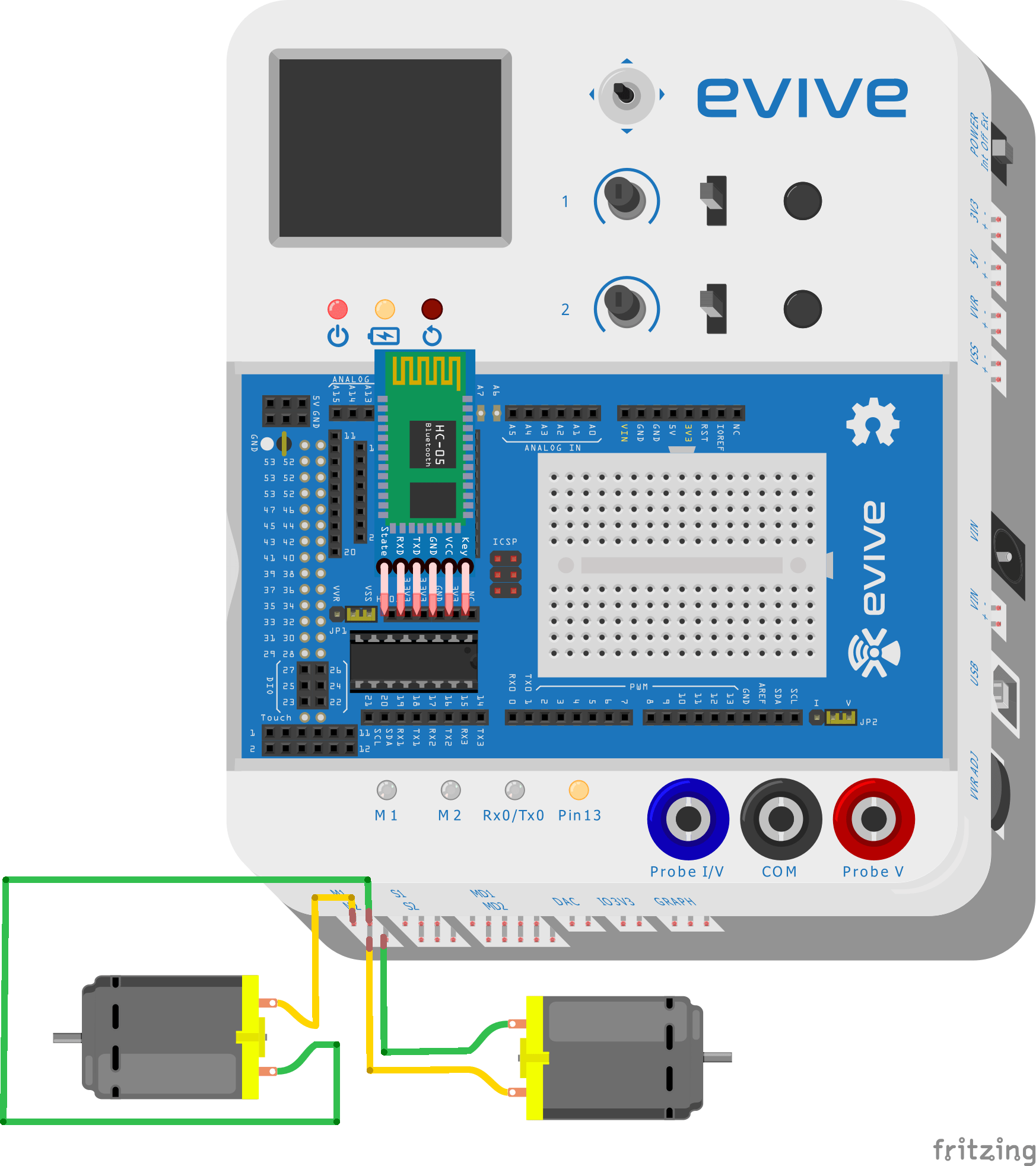
Circuit Diagram
Do the following connections:
- Left Motor: evive Motor Channel 1
- Right Motor: evive Motor Channel 2
- Bluetooth: evive Bluetooth header as shown in the figure.
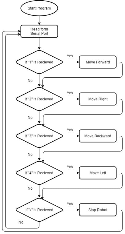
Flow Chart
At a time, the mobile robot can move forward, backward, right or left and stop. Given below is the flow chart:
Arduino Code
We are using Arduino Bluetooth Controller App to send command to the robot via Serial port 3.
Given below is the example code:


