
Introduction
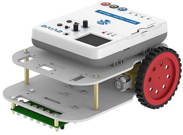
A Line Follower Robot, as the name suggests, is an automated guided vehicle, which follow a visual line embedded on the floor or ceiling. Usually, the visual line is the path in which the line follower robot goes and it will be a black line on a white surface but the other way (white line on a black surface) is also possible. In this project we will make a black line following robot.
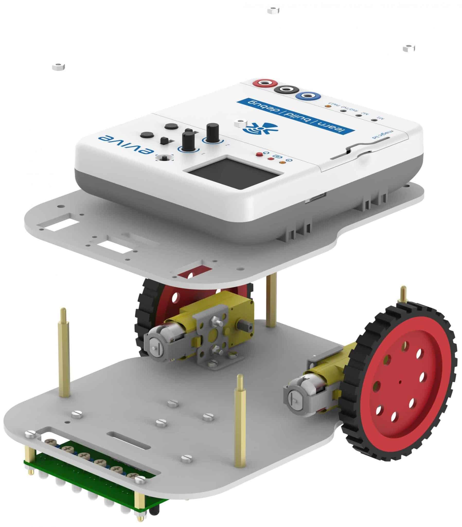
Assembly of the Robot
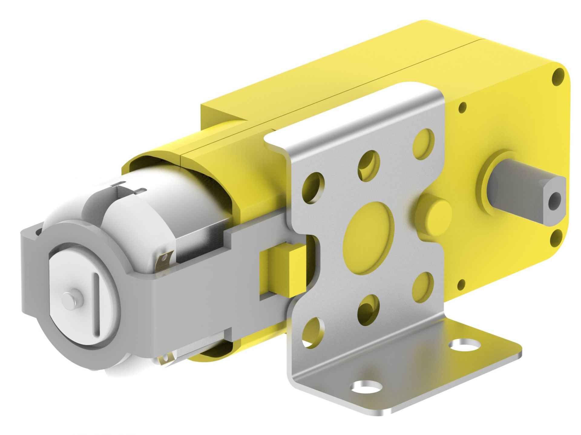
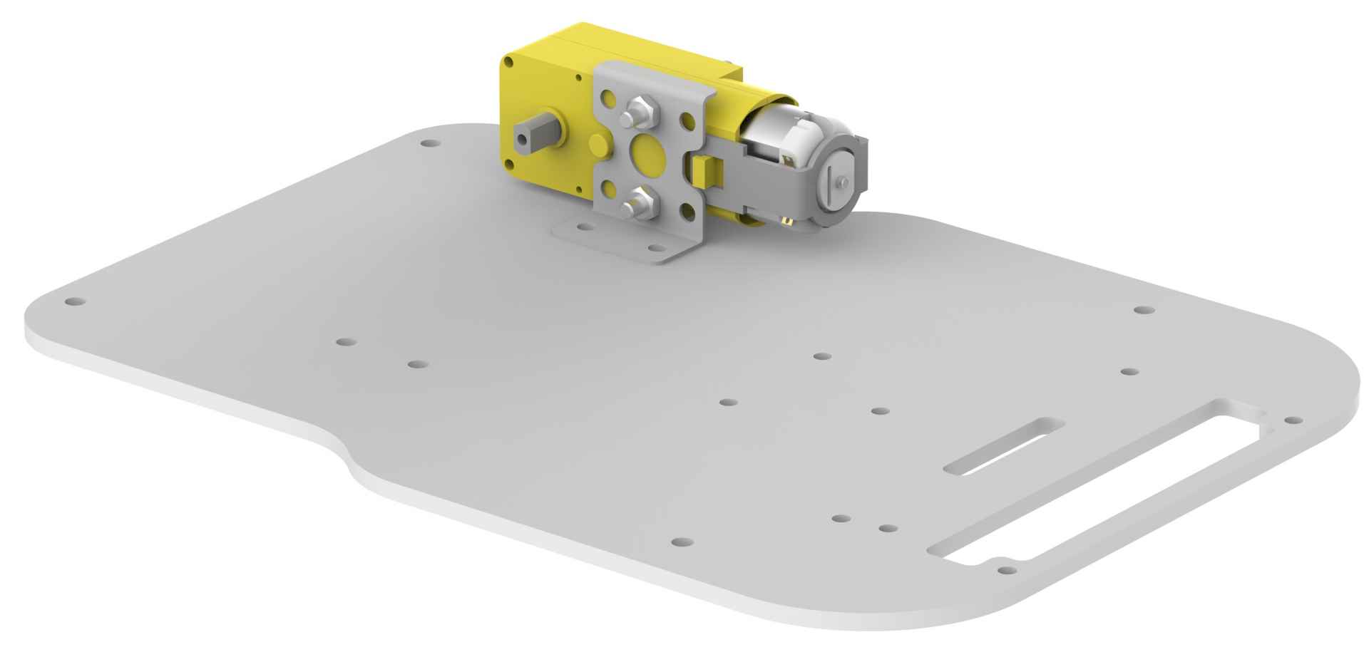
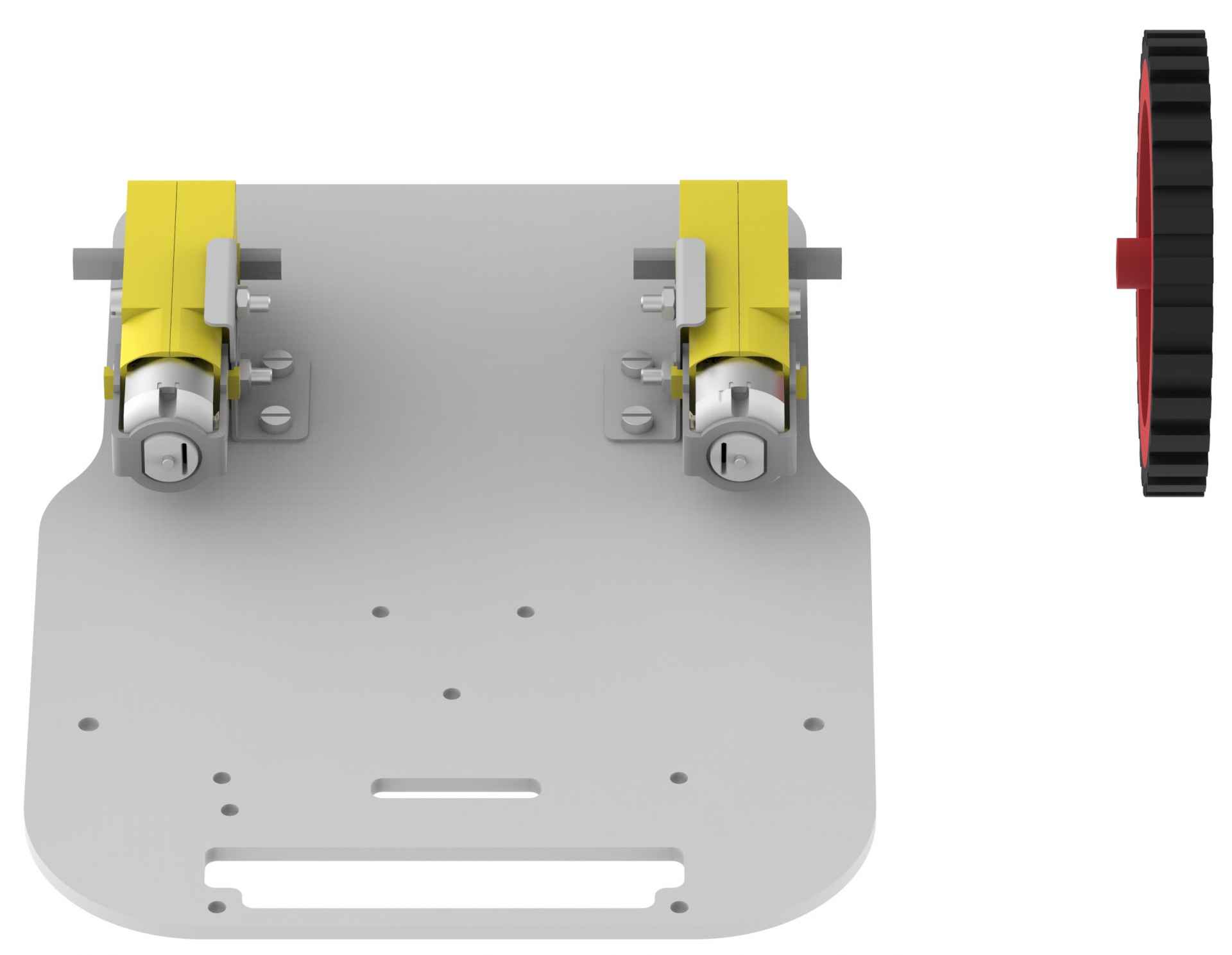
- Place an angle bracket on the motor as shown in the figure. Note that the racket should be placed on that side of a motor which has a circular extrusion coming out of the yellow body (white plastic body if you have a white motor). If you are preparing a right hand side motor, then your assembly should look like as shown in the figure, otherwise you have to mount the bracket in the upside-down position (for left motor).
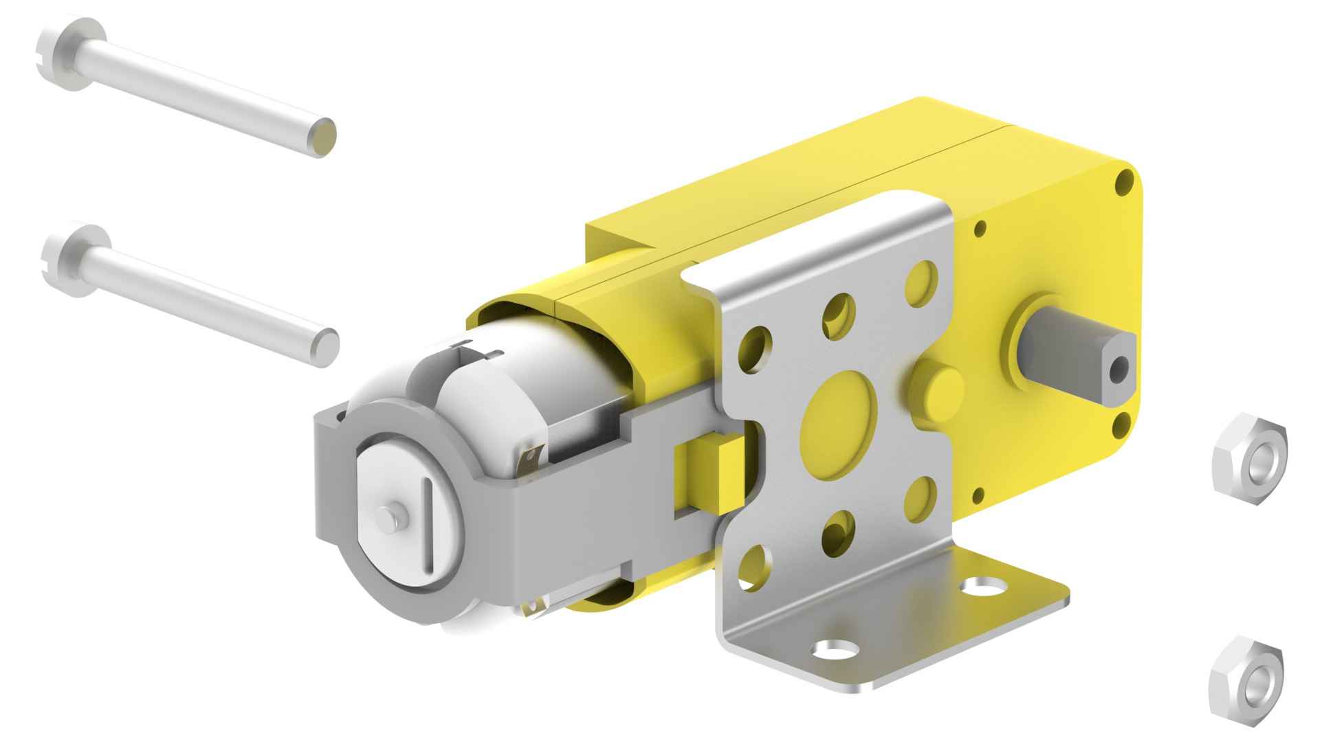
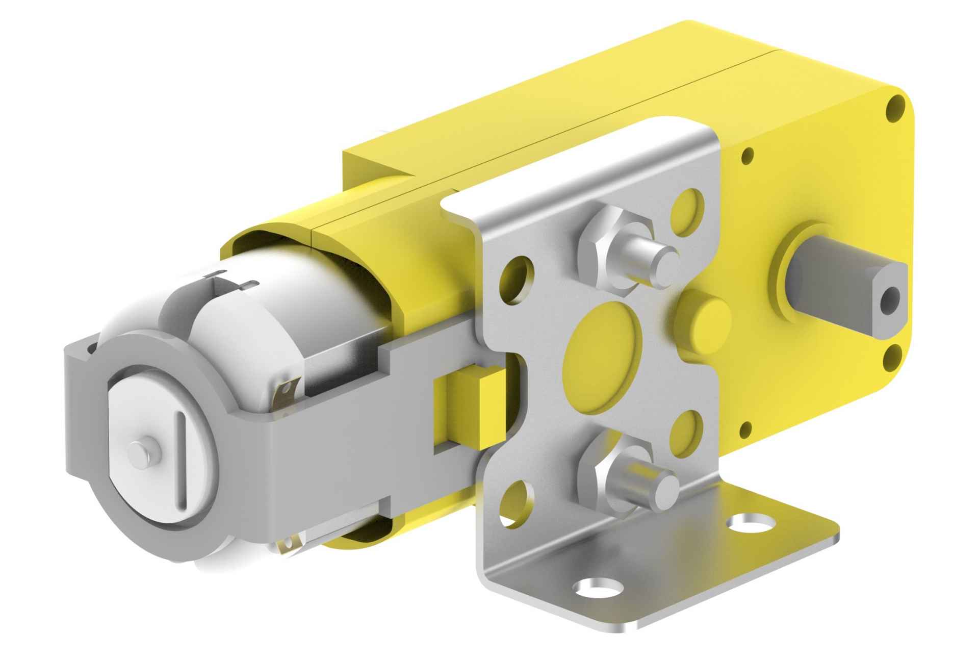
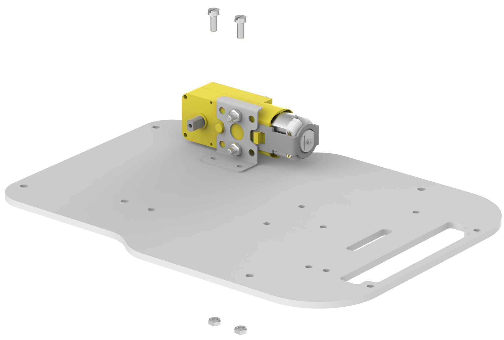
- Using two 12mm M3 bolts and two M3 nuts, fasten the motor and brackets.
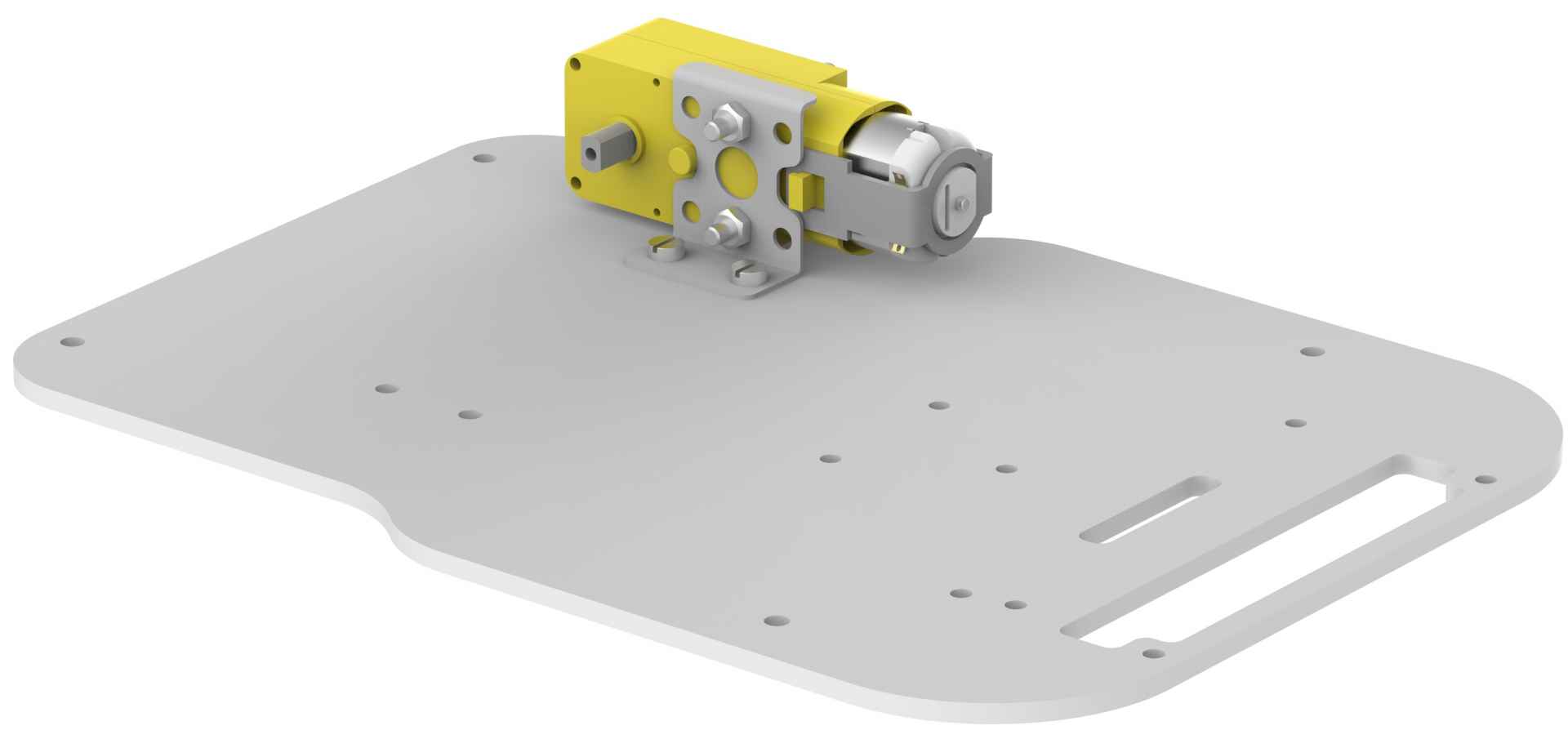
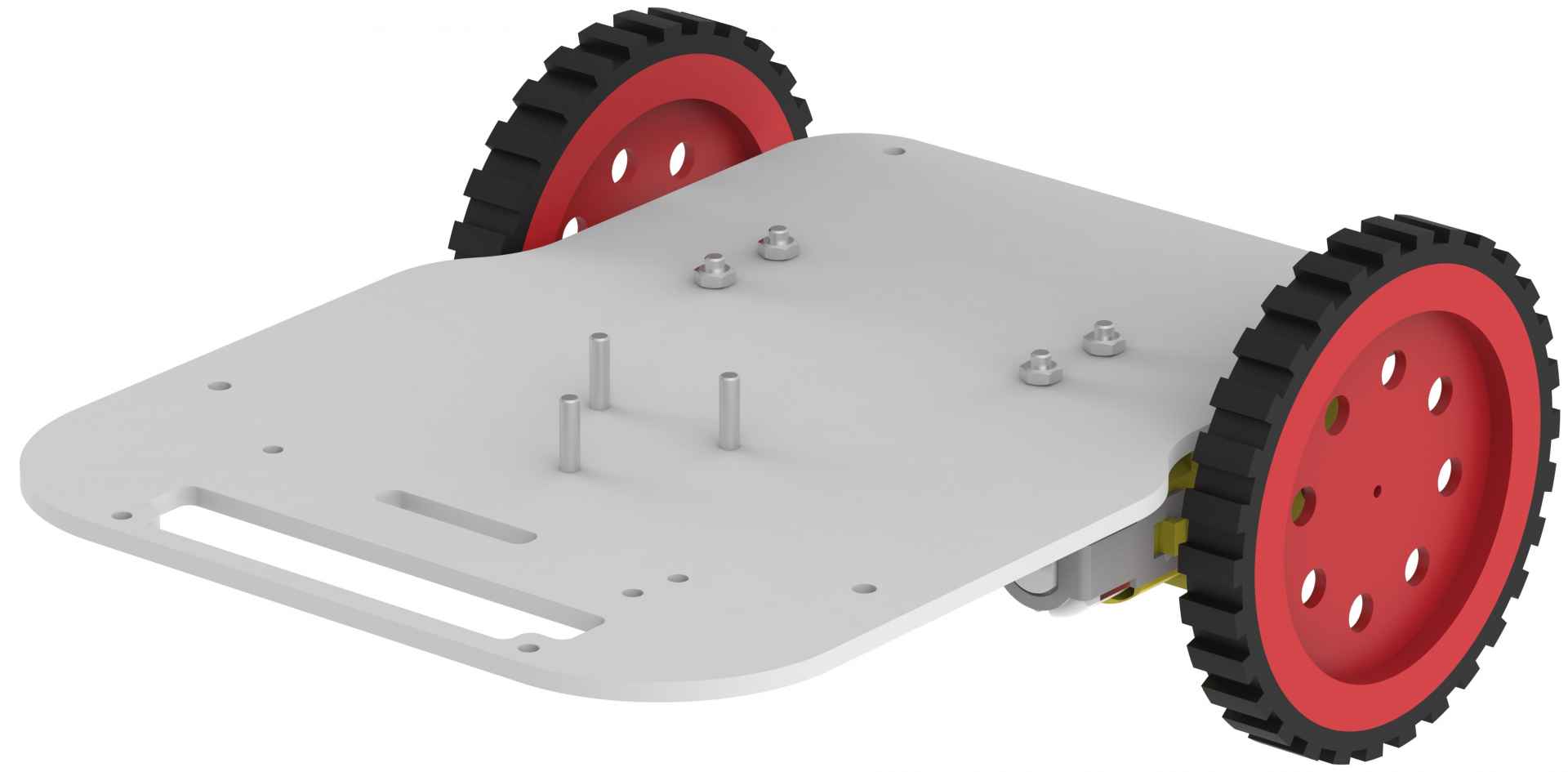
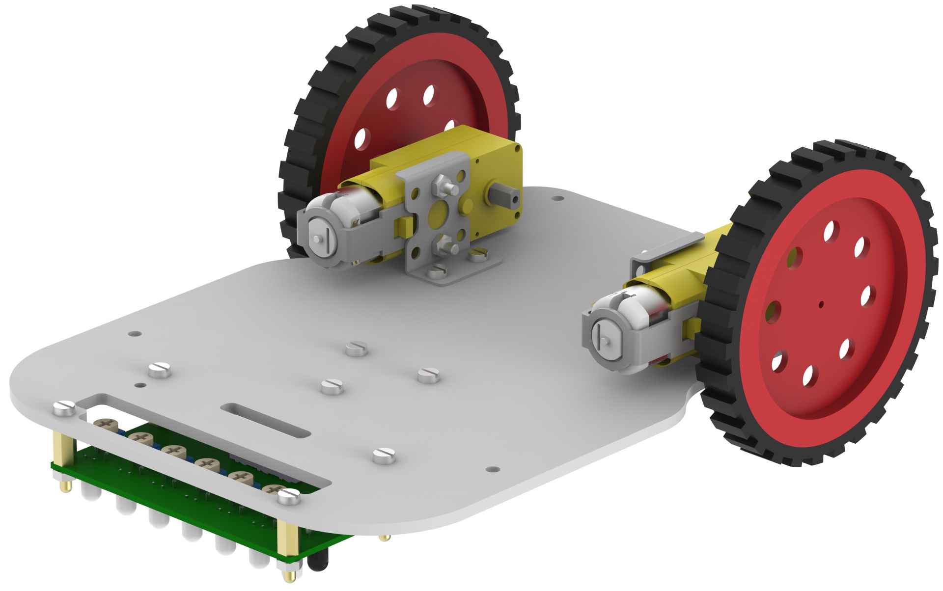
- Place the left motor bracket assembly on the lower base plate in the mounting holes provided.

Note that, as the base plate is symmetric, you should keep in mind which motor is for right side and which one for left before mounting them.
- Fasten the motor using two 8mm M3 bolts and two M3 nuts.
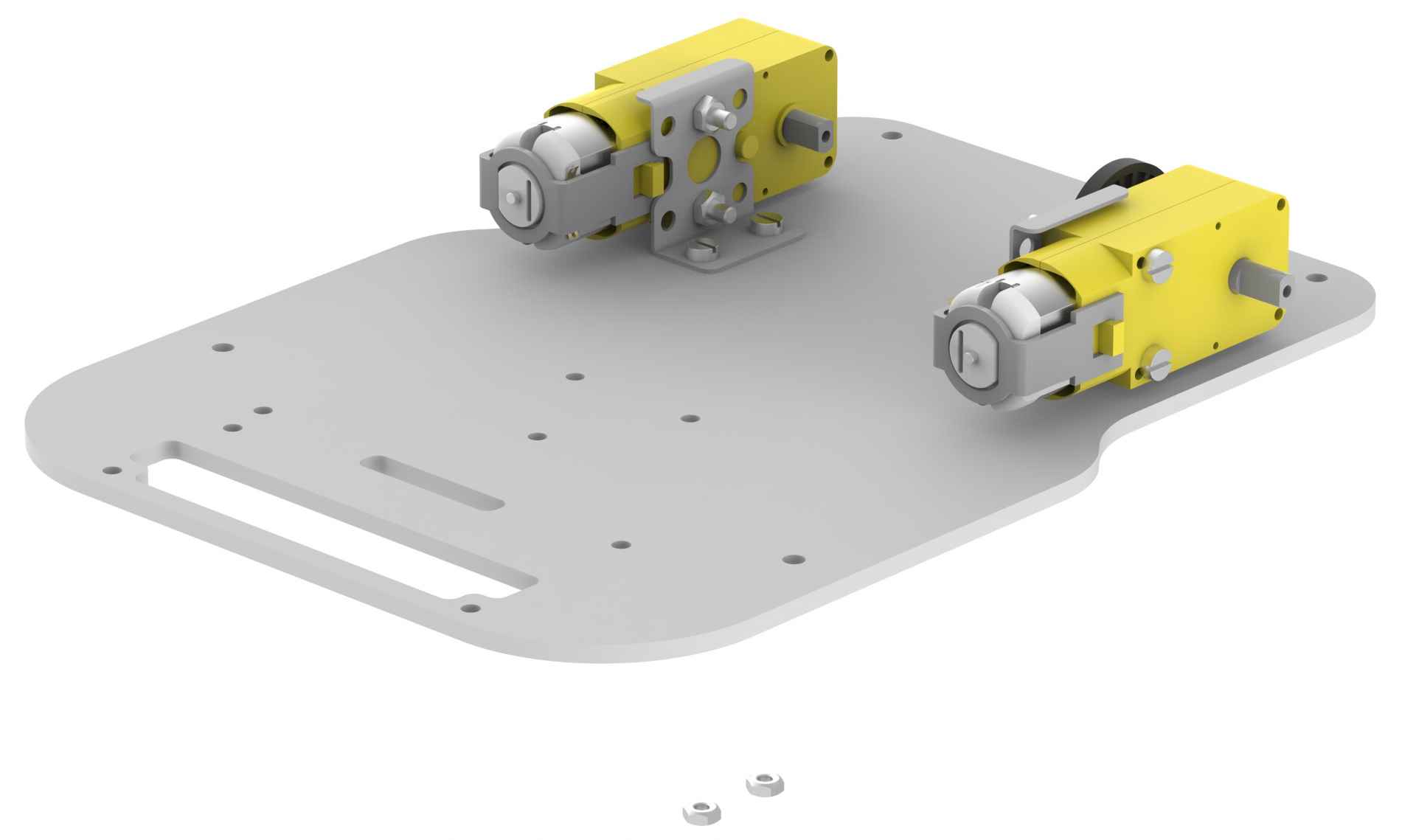
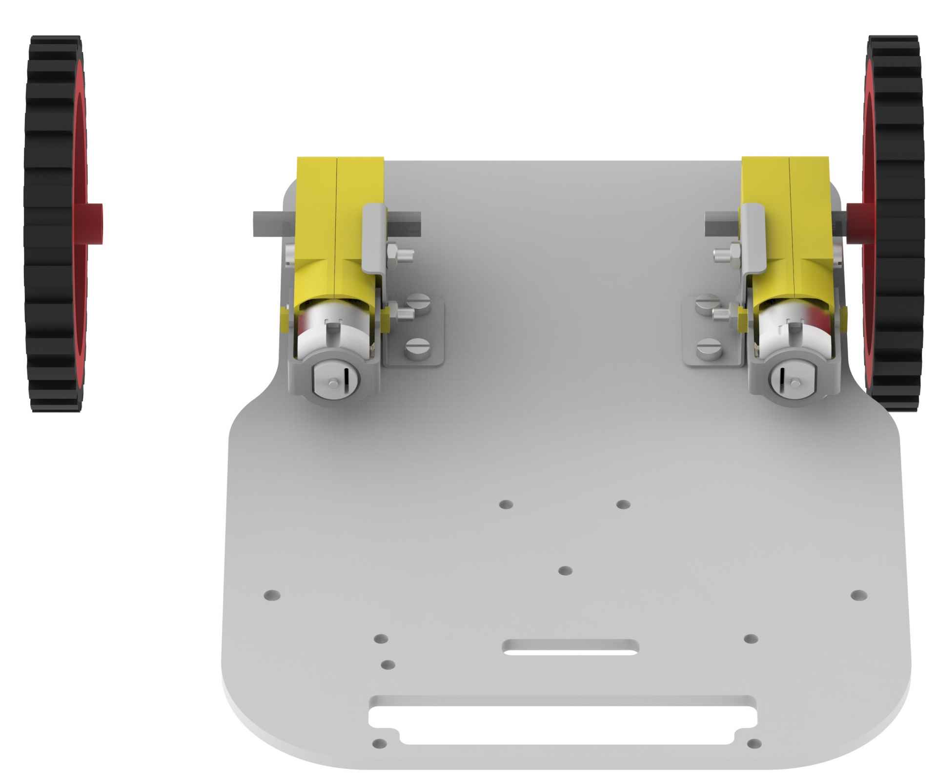
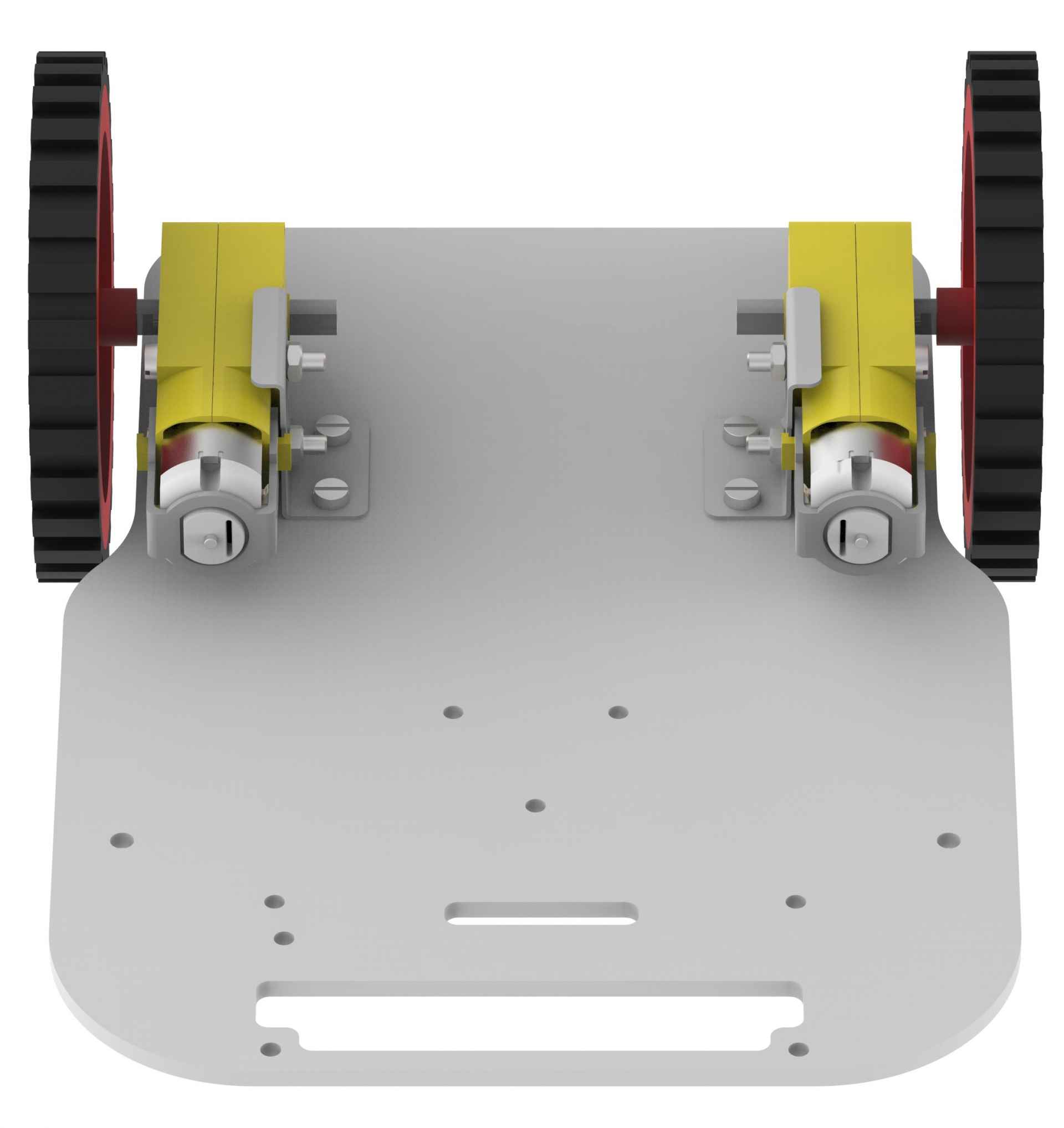
- Similarly mount the right motor using nuts and bolts. Ensure that you have mounted the motors in the exact way as shown in the figure.
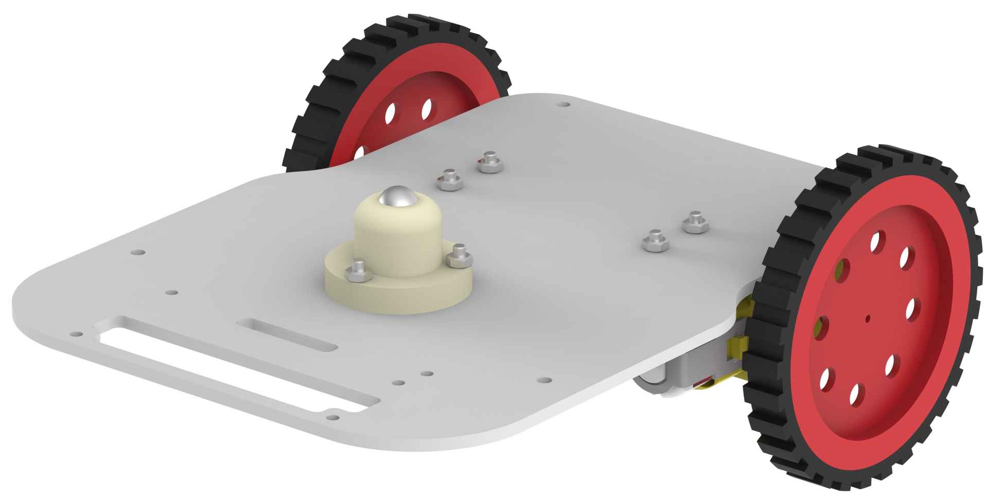
- Then, gently attach wheels on the motor shaft as shown in the figure.
- Turn the lower base plate upside down and mount the castor wheel on the mounting holes provided on the base plate. Using three 12mm M3 bolts and three M3 nuts to fasten the castor wheel.
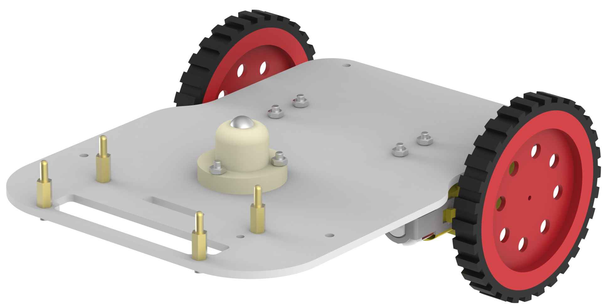
- Using 8mm M3 bolts and female side of the 10mm standoffs, mount four standoffs on the lower base plate as shown in the figure.

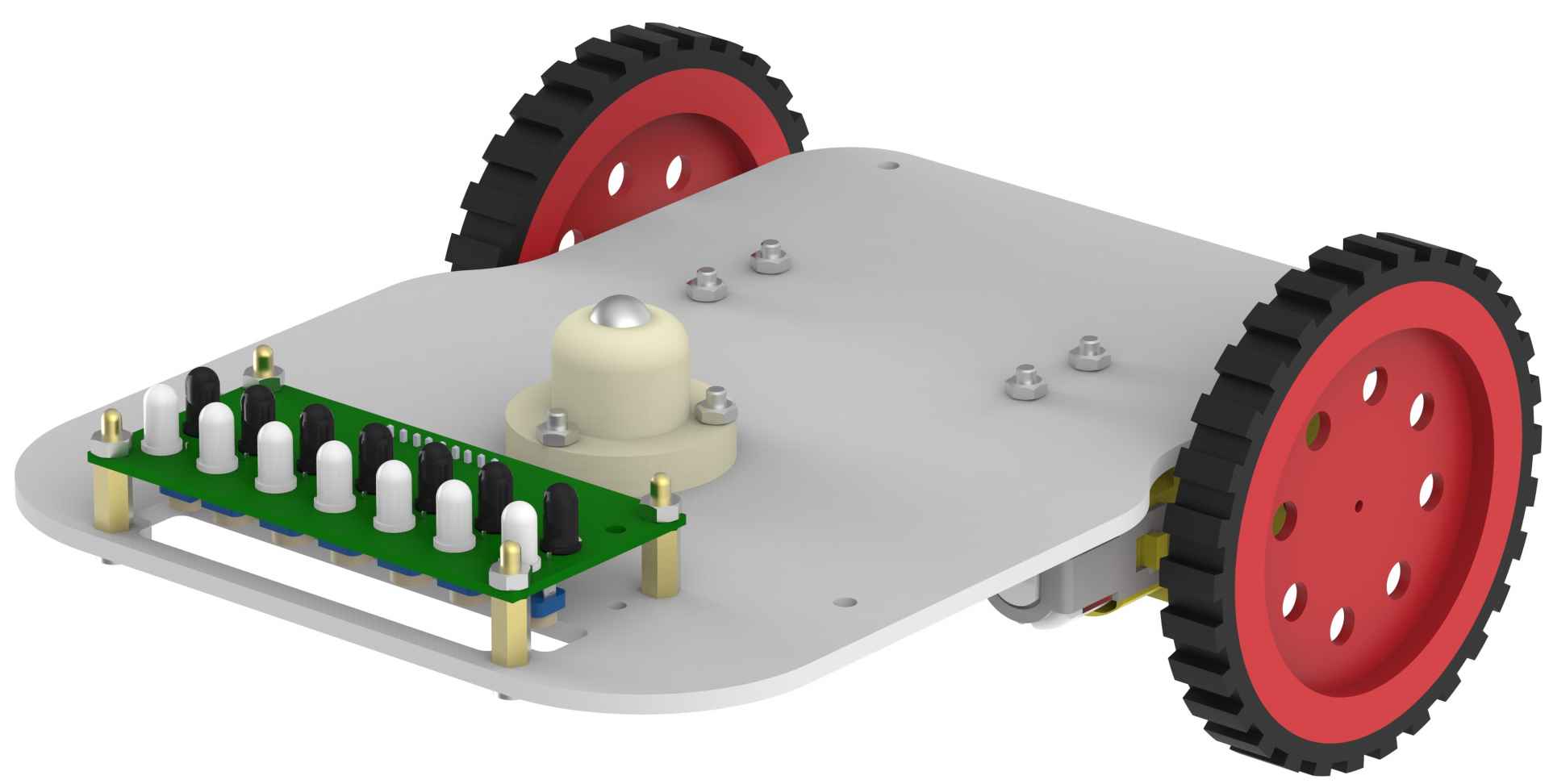
- Place the line following sensor on the standoffs as shown in the figure.
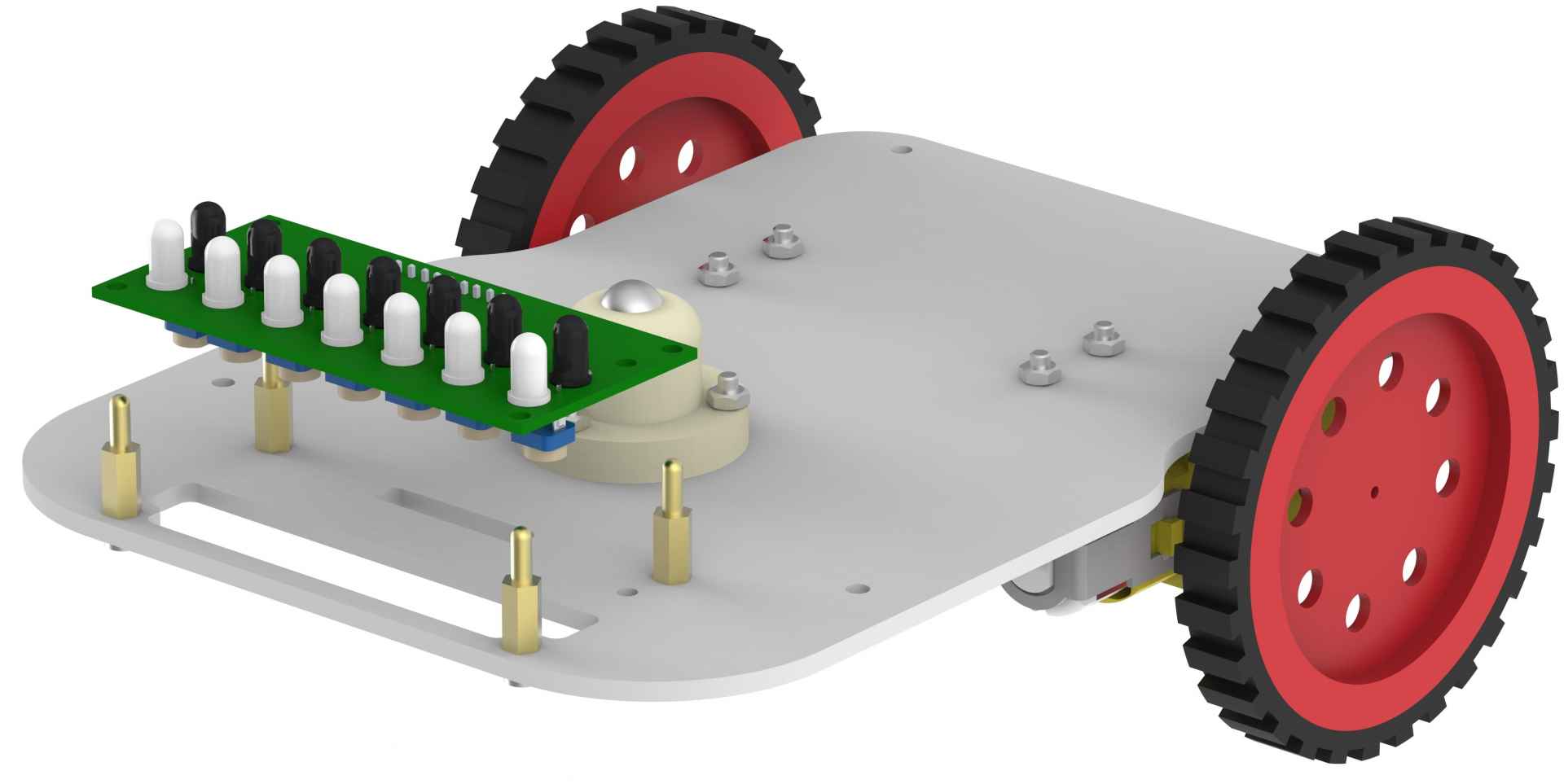
- Using M3 nuts, fix the sensor to the lower base plate.
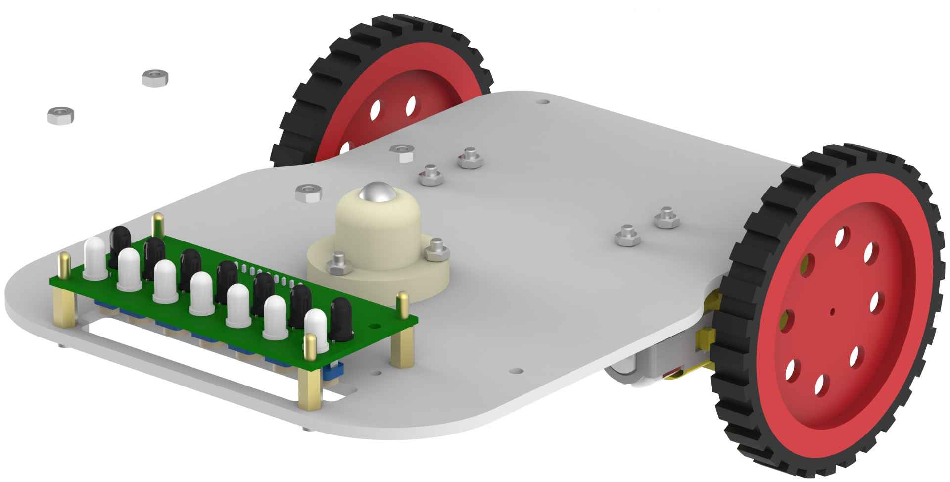
- Turn the lower base plate back to initial position.
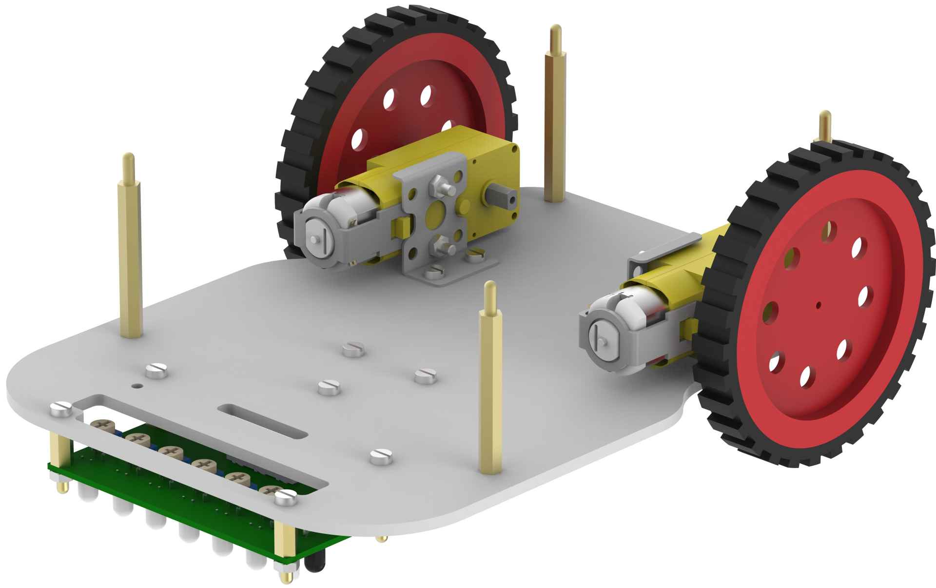
- Now, using 8mm M3 bolts, mount 40mm standoffs on the holes provided on the base plate.
- Mount evive on upper base plate using two 12mm M3 bolts. Note that if you are not using encoders, then you can mount evive with all four bolts.
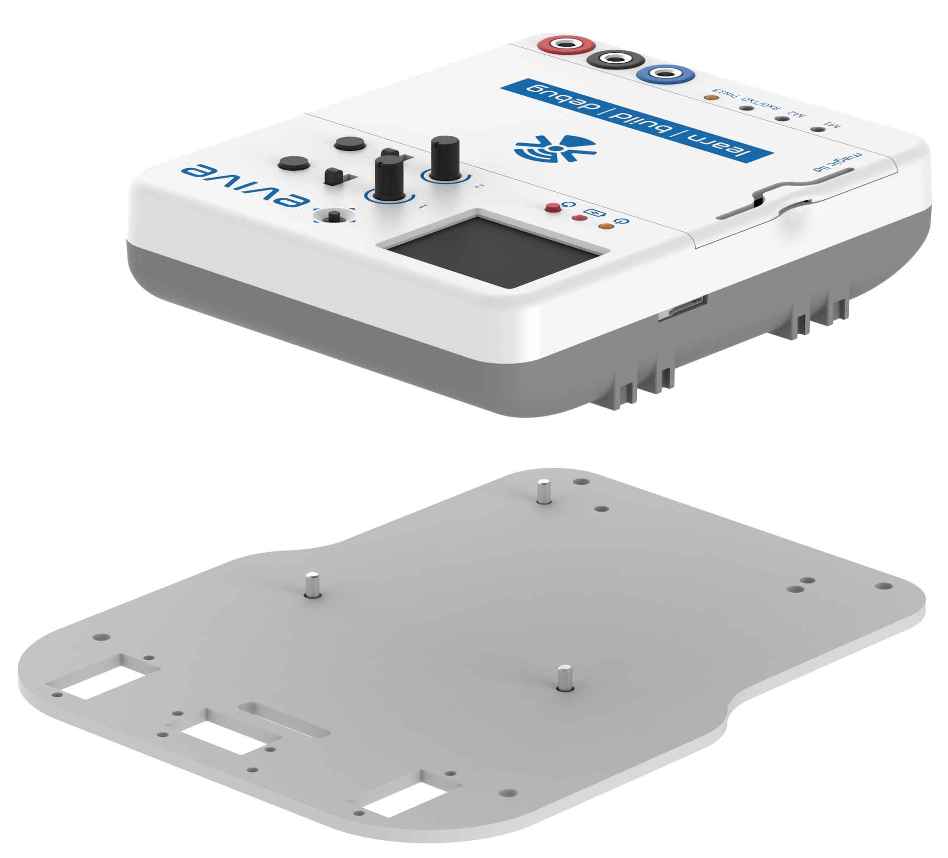
- Finally place the upper base plate on the standoffs of the lower base plates.

- If you want to increase the height at which the upper base plate is mounted, then you can do it, by attaching another 10mm standoffs on the 40mm standoffs.

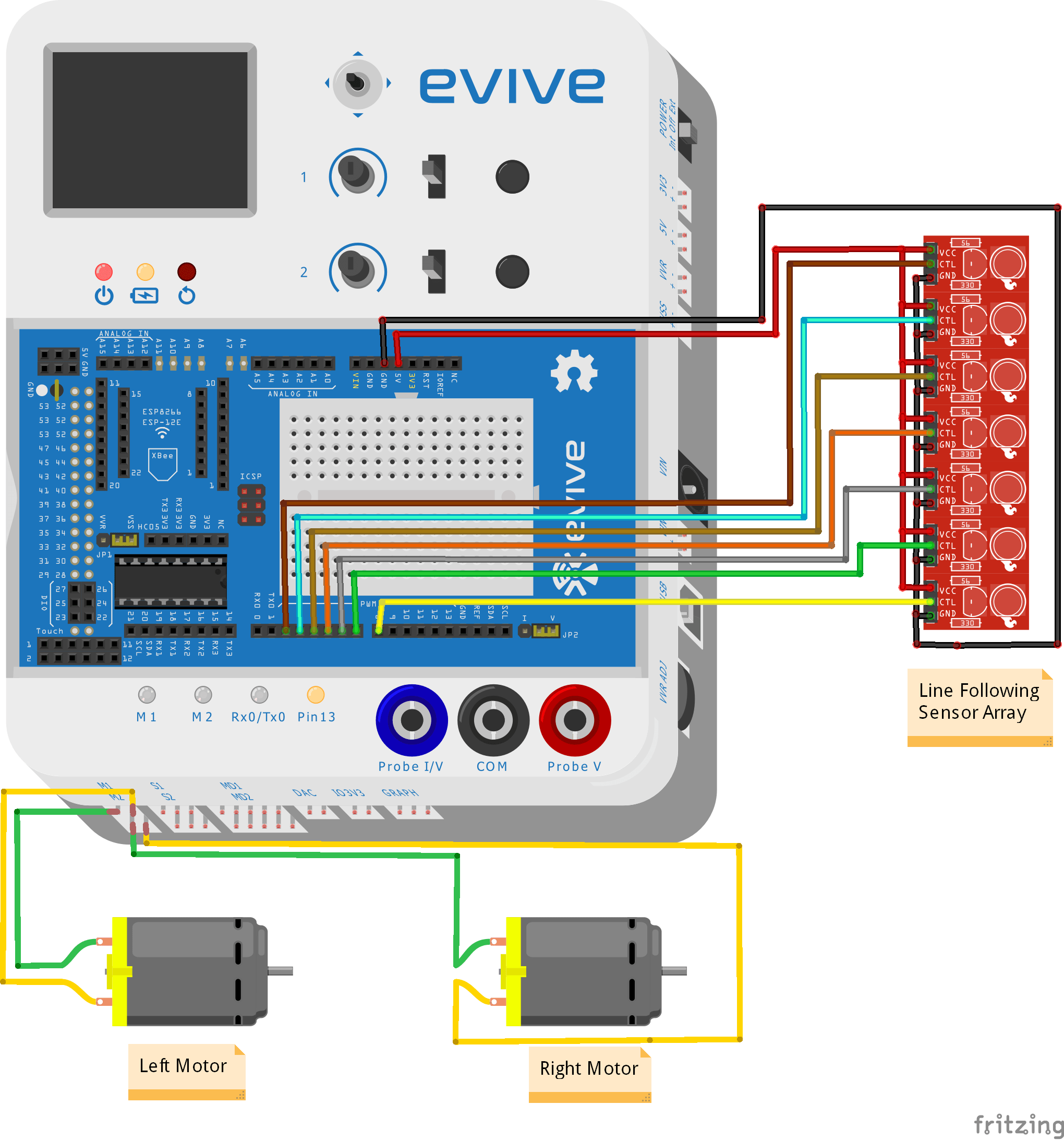
Circuit Diagram
Do the following connections as shown in the figure:
- Left Motor: evive Motor Channel 1
- Right Motor: evive Motor Channel 2
- Line Array Sensor: Digital Pin 2-8


 I Aradhya Gupta I 7th I DL DAV Model School SB I CODEVOUR 2022 2-16 screenshot")


