
Introduction
A light tracker tracks the direction of the incoming light. It can be used along with solar panels which are programmed to move in the direction of the sun to receive the maximum amount of incident light. Solar trackers are built on the same principle to capture maximum sunlight.
In this project, we will be building a light tracker using light dependent resistors to detect the direction of incoming light from the torch of your Smartphone and two servo motors to align in that direction.
Ready. Set. Go!
Assembly
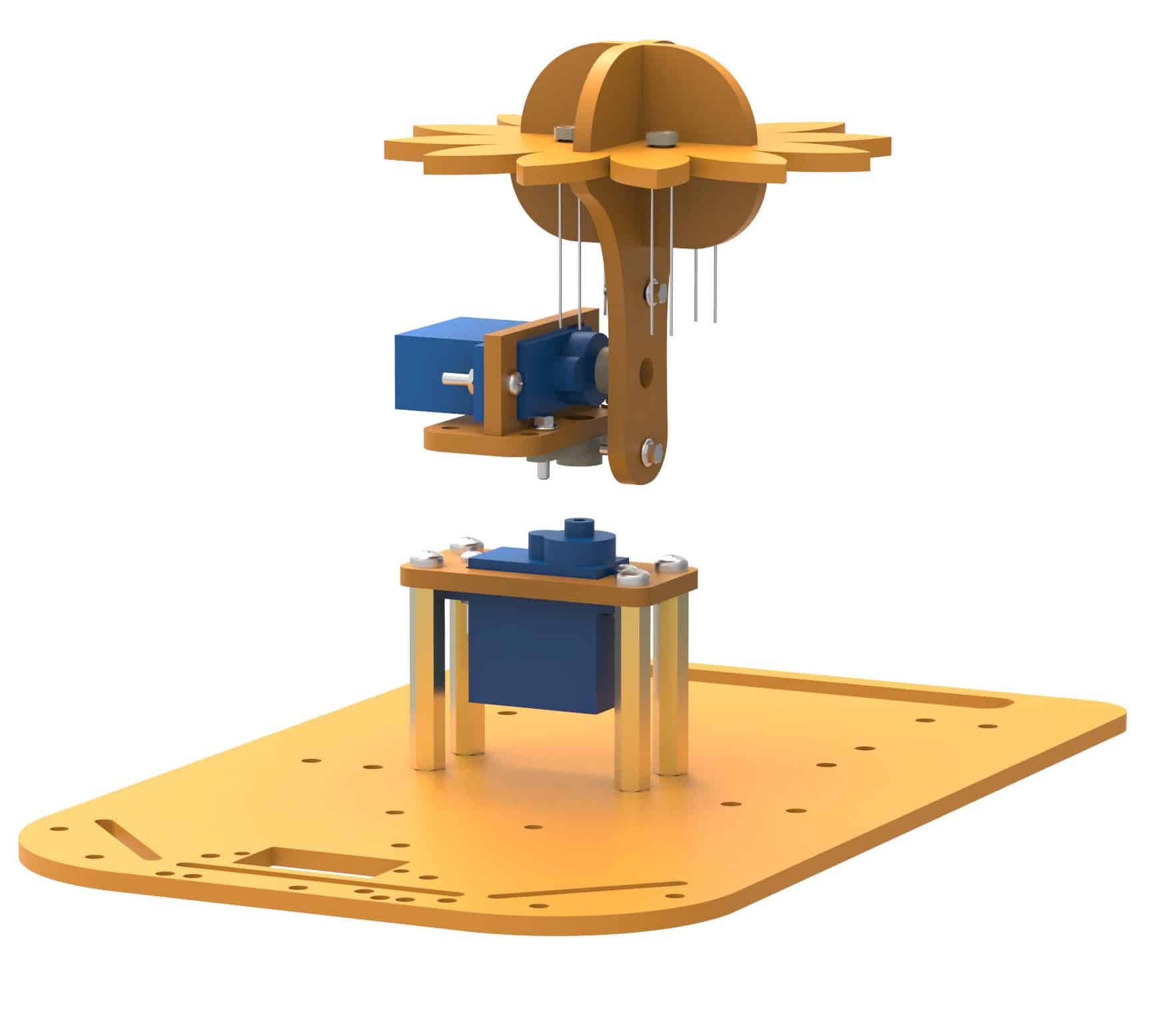
The assembled robot is shown in the following figure: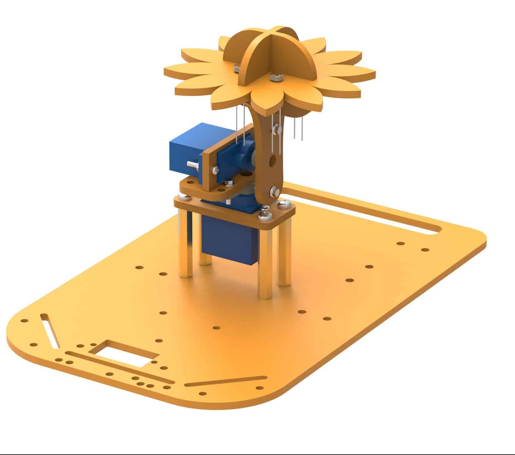
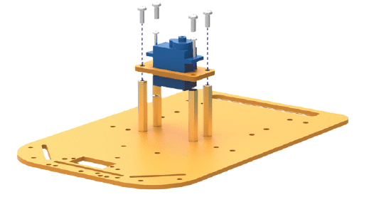
- Attach 30 mm standoffs to the chassis at the positions shown. Fasten using M3 bolts of 8mm length.
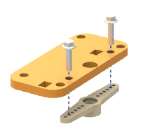
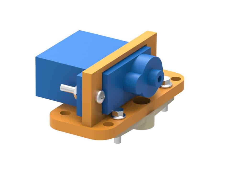
- Insert a servo motor in the base servo holder and fasten it to the holder using M2 bolts of 12mm length and M2 nuts.
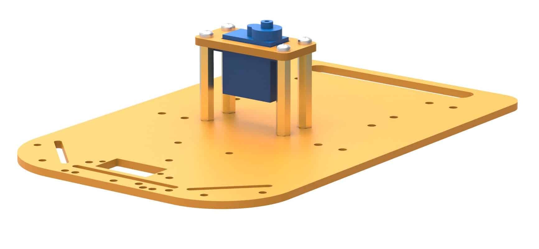
- Fasten the motor holder at the top of standoffs using M3 bolts of 8mm length.
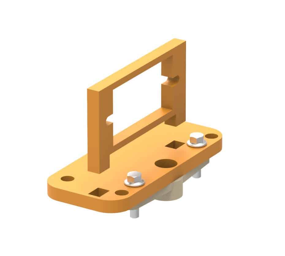
- Our light tracker requires two servos, one for rotation about each axis. This is one of the two. Also, to produce combined rotation, both the motors should be connected. Insert the second motor in the servo motor holder. The same assembly shall carry the micro horn which fits into the first motor. Fasten the horn to the servo motor holder using self-threading M2 screws, as shown in the corresponding image.
- Fix the motor holder to the base through the rectangular slots available.
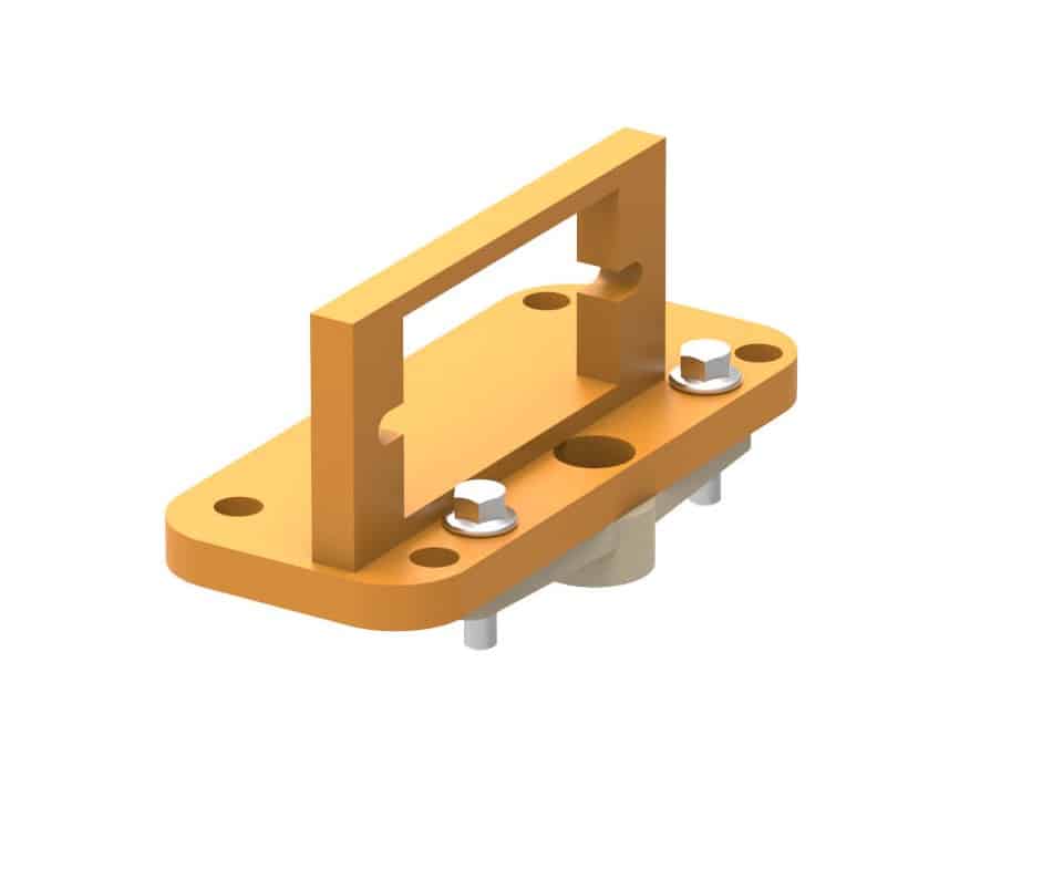
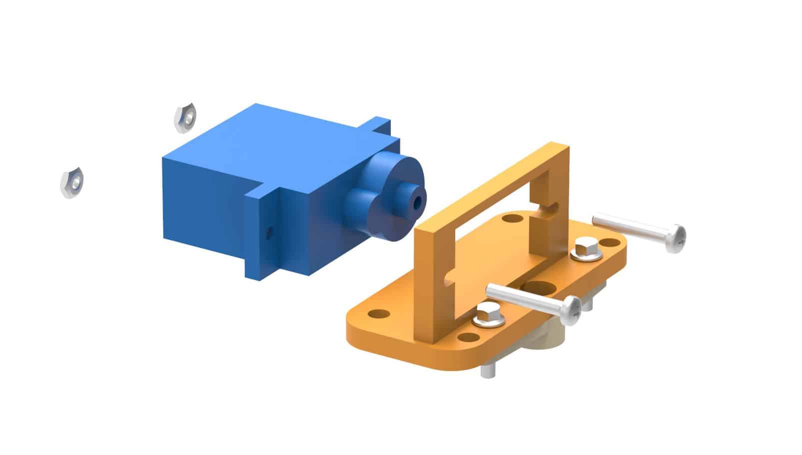
- Insert the second servo in the slot on the holder and fasten using M2 bolts and nuts.
We have assembled the individual motors. Now, we will assemble our 4 LDR sensors which will detect incoming light from the four directions.
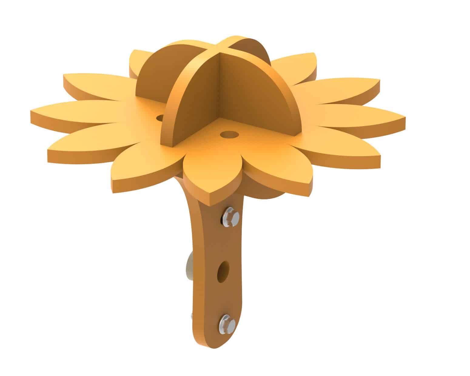
- Arrange the light tracker plates 1 and 2 provided with the kit as shown in the image below.
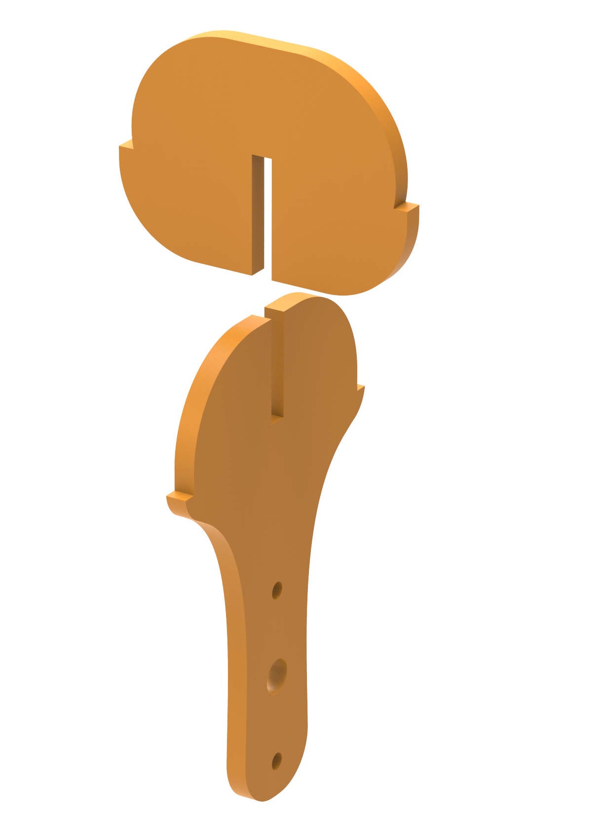
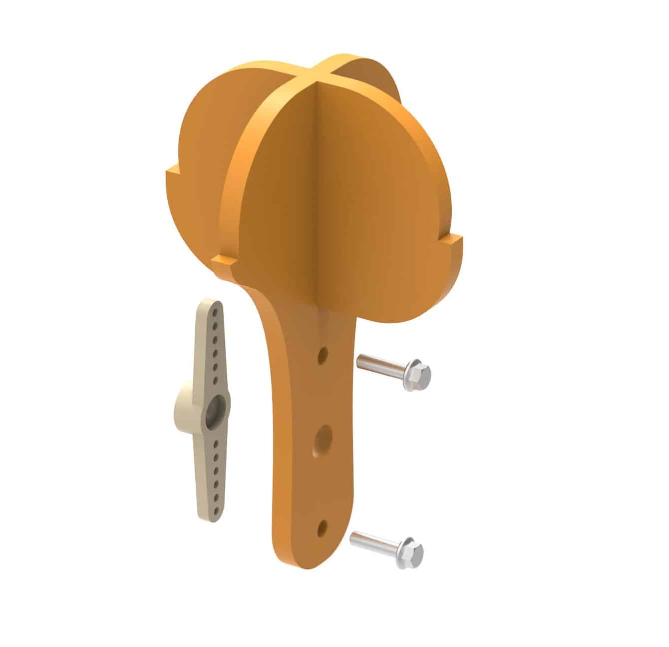
- You can see how the surface has been divided into 4 sections. One LDR will be inserted in each hole. This, along with the LDRs will be attached to the servo. Through the combined rotations of the 2 servos, this assembly will be able to receive light from all possible directions. Fasten a servo horn to it using M2 screws, as shown.
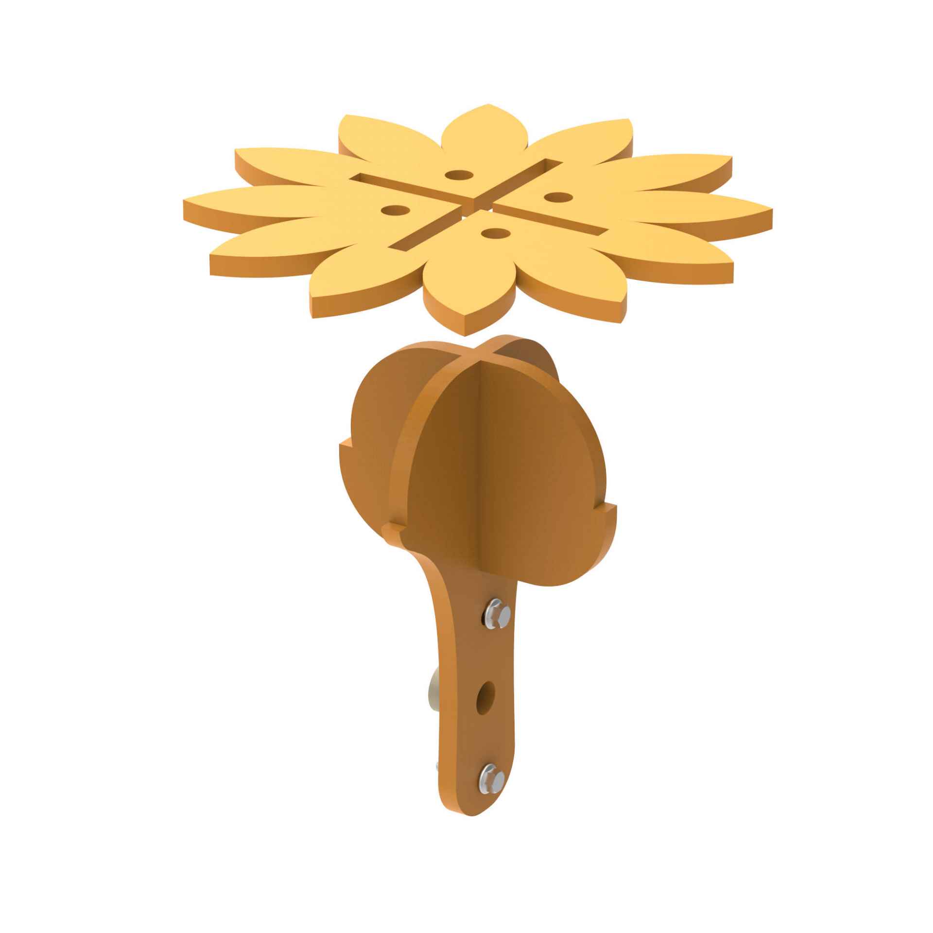
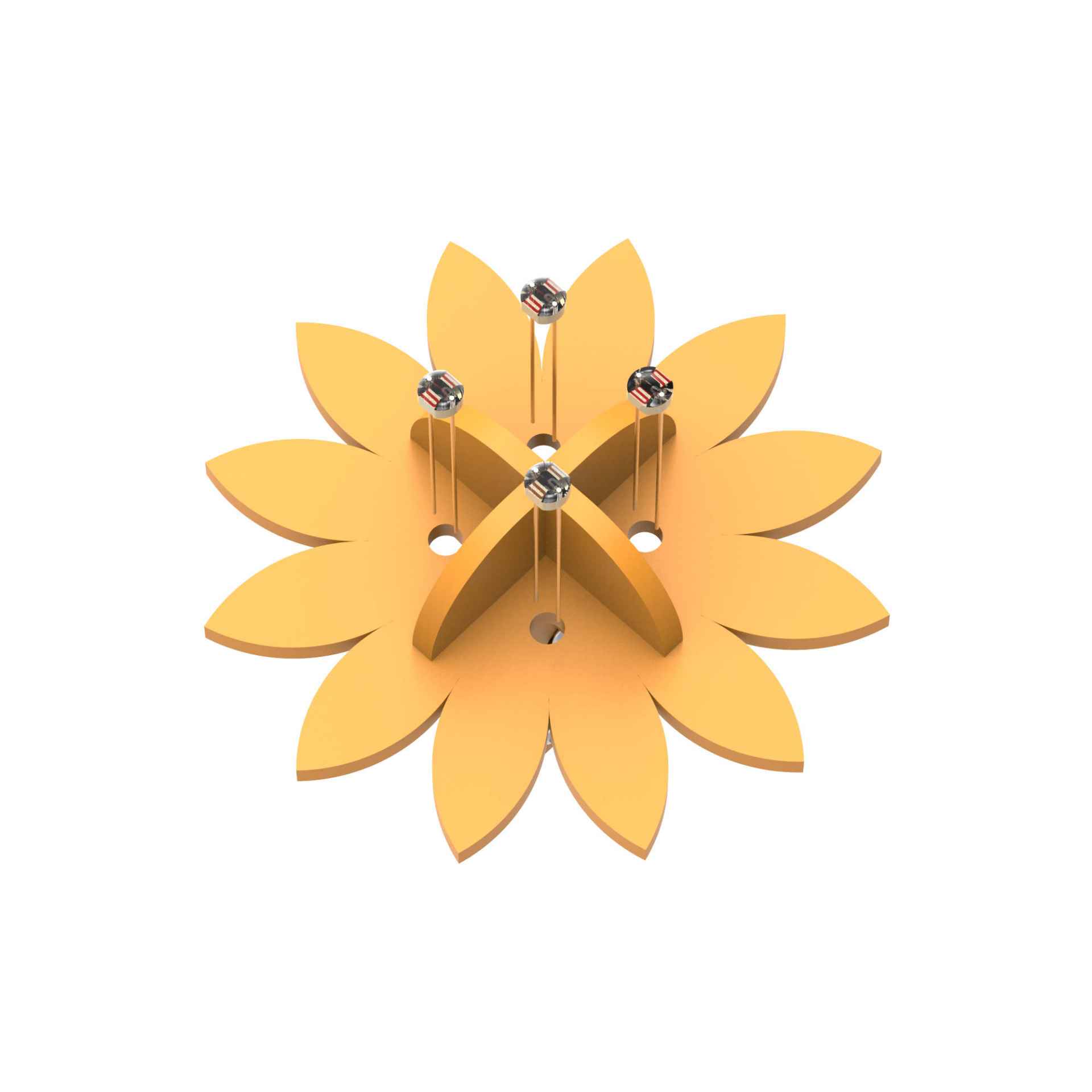
- Make a sunflower-shaped cutout using a hard paper as shown below and paint it with your favorite color. You need to make a + shaped cut at the center and four small holes in each section of the cutout. Then place it on the top of the light tracker plate assembly by matching the slots, as shown.
- Insert LDRs (light dependent resistors) into the holes made.

- There is a free horn on our sunflower like assembly. We will lock our second servo motor to the horn through the screw provided with servo accessories. Using evive controls menu, set the servo angle to about 90°.
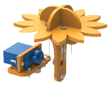
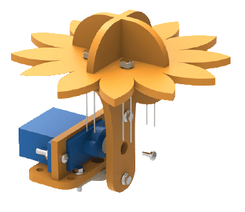
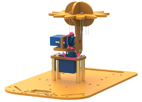
- There is a free horn at the bottom of this assembly which we will connect to the remaining servo. Now you can see how each servo’s individual rotation will provide an all-around rotation of the sunflower-like structure on top hence ensuring that it is able to detect the light falling on different sections.
Add-Ons
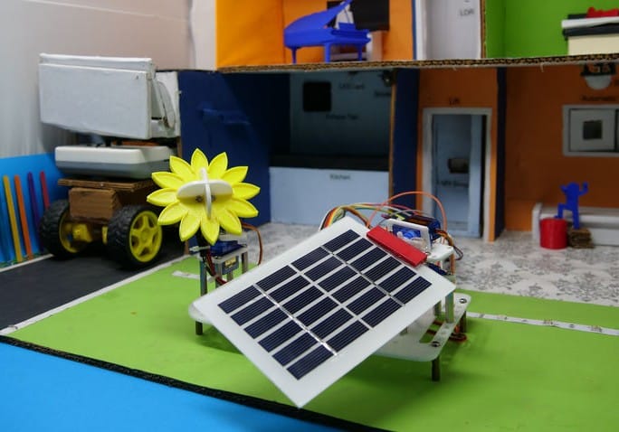
Here, the most popular use of the Sun Tracker is when we attach Solar Panel. In Solar Panel, if the Photoresistors are, then the solar panel will then check which part of it is receiving more light. Thus, adjusting the position accordingly. Which results in increased efficiency.
We have then placed this Sun Tracker in our home.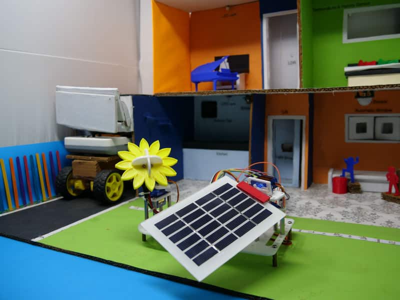
Circuitry of the Robot
Connect the LDRs and 10 kOhm resistors directly to the breadboard. Make the remaining connections using jumper
wires. Refer to the circuit diagram for ensuring proper connections.![]()
Logic
From the assembly, you can observe that the four LDRs are separated by the wall. Each LDR will detect light falling on its section. We will number each LDR for reference. If both the servos are at the 90-degree position, then the sunflower will be facing upward as shown in step 12 of assembly. The top left LDR will be named LDR1. Similarly, we will name LDR2 (top-right), LDR3 (bottom-left) and LDR3 (bottom-right).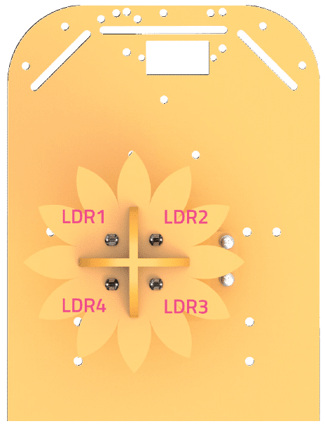
- Upper Region – LDR 1 and LDR 2
- Lower Region – LDR 3 and LDR 4
- Left Region – LDR 1 and LDR 4
- Right Region – LDR 2 and LDR 3
We will also name the two servos – Vertical (servo on the base) and Horizontal (servo on the top).
Using the horizontal servo, we will reduce the difference in the light falling on the upper region and lower region to zero. If the light is coming from the upper region, then the upper region LDRs will have higher reading as compared to the lower region. Hence we have to rotate the horizontal servo motor forward incrementally.
If the lower region has higher value, then we will move the sunflower backward incrementally.
To move the sunflower sideways, we will use the vertical servo. Whenever there is a difference in the values of the left region and the right region, it will move to reduce it to zero. If the light is more on the left region as compared to the right region, we will decrease the servo angle by 5° each time until the difference is zero. If the light is more on the right region as compared to the left region, we will increase the servo angle by 5° each time until the difference is zero.
To decide the direction in which the servos should move, we will consider the total amount of light received on a region, i.e. the sum of readings at LDR analog pins.
Scratch Script
The code is written in two halves, one for each motor. Initially, both are set at an angular position of 90 degrees as shown in the main script.
CalibrateVerticalServo and CalibrateHorizontalServo are two blocks defined to track light.
Create variables LDR1_Value, LDR2_ Value, LDR3_Value and LDR4_Value to store the analog value of the LDRs connected to analog pin A0, A1, A2 and A3 respectively.
Create variables, HorizontalServo and VerticalServo to store servo angle. Also, create variables Average1 and Average2 to store the average LDR value of the upper region and lower region.
For CalibrateHorizontalServo block, Average1 represents the average light falling on the upper region while Average2 represents the average light falling on the lower region. Depending on which region receives more light,
we slowly change the variable HorizontalServo. Observe that we only check the magnitude of difference in the variables using the abs block.
The physical angle will only change when we use the set servo pin angle block to set the angle equal to the variable HorizontalServo.![]()
![]() Now the entire script is ready. Upload it to evive as done in the previous chapters. To check if the light tracker is working or not, turn on the flashlight of any smartphone and move it over the robot. It should start following the light.
Now the entire script is ready. Upload it to evive as done in the previous chapters. To check if the light tracker is working or not, turn on the flashlight of any smartphone and move it over the robot. It should start following the light.![]()
Conclusion
With this, your very own solar tracker is ready! Now watch as it follows you and your Smartphone’s light wherever you go!


