
Introduction
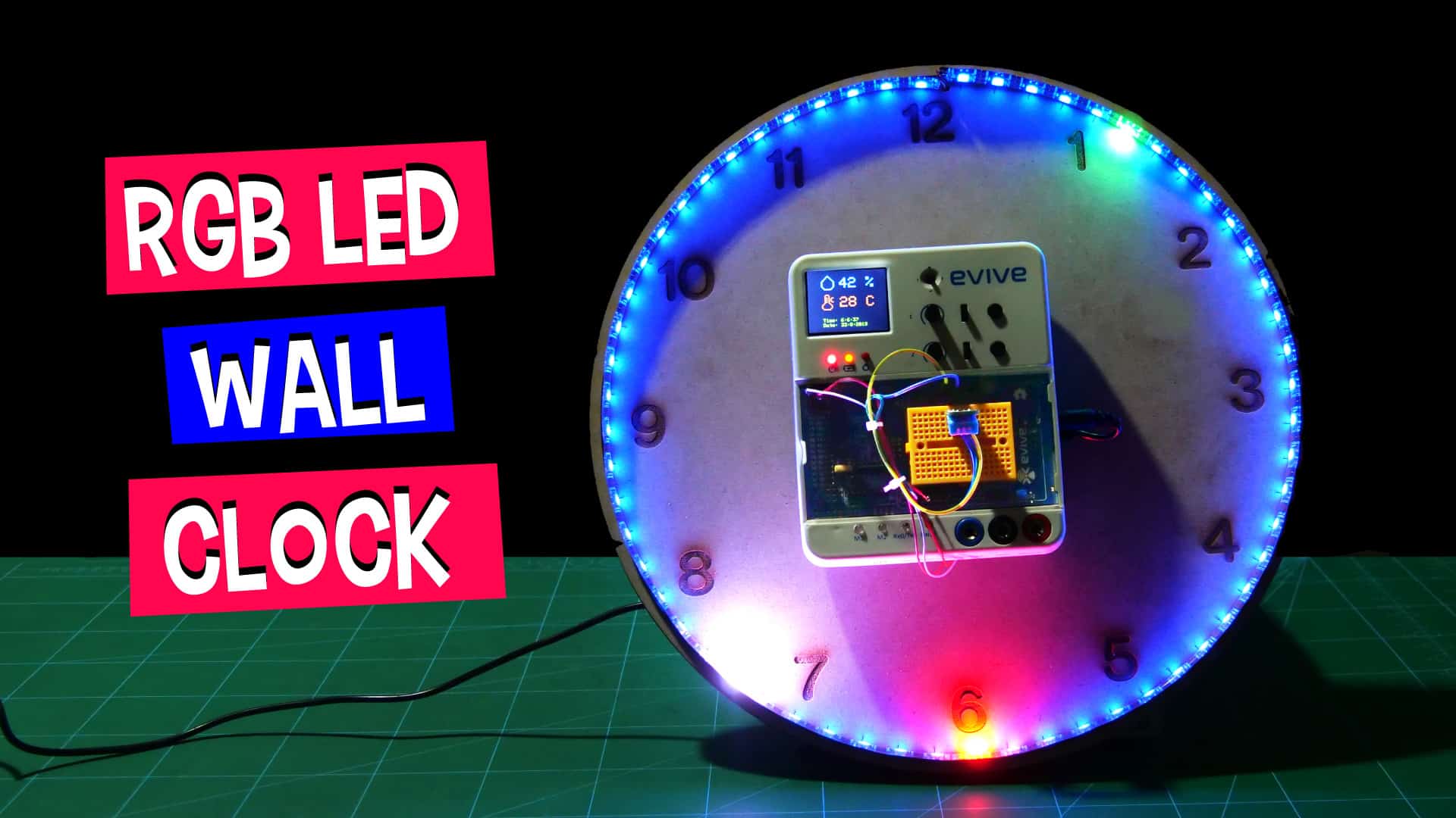
What’s that one thing that can transform your living room from plain and boring to vibrant and attractive? The wall clock! And that’s what we’re here for today: making a DIY RGB LED wall clock that’s not only beautiful but also smart. Not only does it tell the time in a unique way using RGB LED strips, but also display the date, temperature, and humidity. There’s no doubt that you’re going to love it!
What makes it so smart? evive and PictoBlox – our powerful graphical programming platform with advanced hardware-interaction capabilities! You can download it from HERE.
Ready to make your living room beautiful and modern? Then let’s get started!
RGB LED in place of Clock Hands
Before we start with the assembly, let’s first understand how we want our clock to work.
As the name suggests us we will be using RGB LEDs instead of seconds, minutes, and hours hands. As we will need the LEDs to represent second and minutes, we will use the RGB LED strip of 60 LEDs for the same.
We will provide a “blue” as the base color to the wall clock. We low down the intensity of the color so that it gives the backlight to the clock.
Also, we need to differentiate between all the three hands. Therefore, we need the LED to turn “white” for each second. And the position of the minute hand will be the place where the LED is “green”. The LED will turn “red” at the position where the hour hand points to.
The minutes and seconds hands will be easy to represent, but the hour hand can be a bit tricky. There are two ways to represent the hour on the analog clock:
- We can only turn the LEDs “red” of the numbers. Which means if the time is 4:30, 4:15 or 4:59, the hour LED will be “red” at four not somewhere between 4 and 5 in all the cases.
All we need to do is, turn every fifth LED “red” after completion of 60 minutes. This is a simple way to do. - The next is to turn the LED “red” in between the numbers to, which is similar to the analog clocks we use at our home. When the time is 4:50 the hour hand is nearer to 5 but not at 5.
There are five divisions in between two numbers. Thus, we will distribute the 60 minutes into those five divisions which make each division to represent 12 minutes. Example, when the time is 4:10, the hour LED will turn red exactly at 4, whereas, at 4:13, the hour LED of the first division between 4 to 5 will turn “red”.
Also, there will be times, where the minutes and hours are the same like 1:05, 2:10, …, 10:50, 11:55 and 12:00. Thus, the LEDs at this moment will turn “pink”.
As our clock is the analog clock and will show time only in 12 hours format, in both the cases we will need to convert the 24hour format into the 12 hours format. How? When the time is between 00 to 12:59, it can easily be represented without making any conversions. But once the time is between 13 to 23:59, we will need to subtract 12 from the hour hand, which is then converted into a 12hours format, making it easy to represent on our analog clock.
Making the Structure of the Wall
Now, that we know what to do, let’s begin with the assembly of the structure of the clock. You can find the design to be laser cut on the MDF sheet here.
Take the base plate with numbers engraved on it.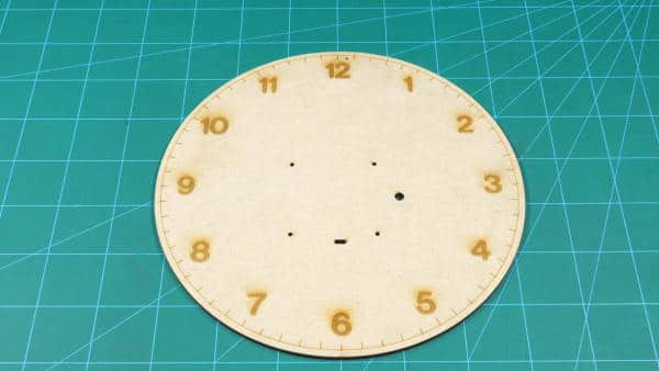
We need to attach the ring on the base plate, thus we will use superglue for the same. 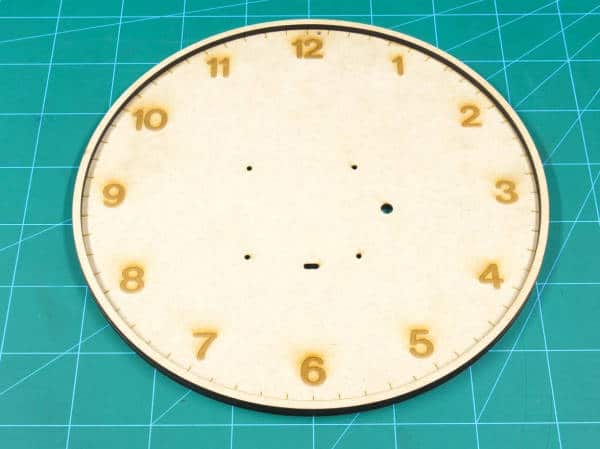
Once done keep the assembly aside.
Testing the RGB Strip
Now, we need to attach the RGB strip, but before that, we need to test the RGB Strip.
We are going to use evive and PictoBlox for the same.
Solder jumper wires to the RGB strip. Connect the RGB strip to evive as given below:
- VCC to 5v of evive
- GND to GND of evive
- DIN to Digital Pin 4 of evive.
Now, to test the strip, we are going to run the test scripts on it. Firstly, connect evive to your computer using a USB cable. Open PictoBlox, select evive from the boards’ option.
Then connect the PictoBlox, by selecting the appropriate COM port.
As we will be to test the RGB strip in real-time, we will be working in Stage Mode. before, working in the stage mode, the first thing we need to do it to upload the firmware to evive. Click on “ Upload Firmware ” button.
Once the firmware is successfully uploaded to evive, it’s time to write the test script. To work with an RGB strip, we need to add the “Lighting Extention” by clicking the “ Add Extention “ button.
Firstly, initialize the RGB by dragging and dropping the initialise RGB strip () with () LED pixels on pin () block. And set the number of pixels to 60. 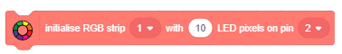
Next, drag and drop () RGB strip () with color () & delay () seconds or () RGB strip () with delay () seconds block and make it glow like the way you want. 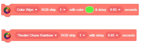
Once done, take the connections out as we need to attach the strip to the clock.
The ring lets you hold the RGB to the clock. Peel of the adhesive paper from the RGB strip and stick it to the inner side of the outer ring.

Once done, pass the wires through the hole next to the number and again bring it to the front from the horizontal slot given in the center.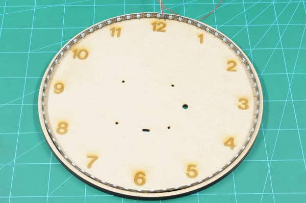
Time to Add the Brain
Take the two hanger plates (one solid and one hollow), these plates will hold evive to the clock and also will be used to hang the clock to the wall.
Take the solid hanger plate and place it on the hollow hanger plate, as the hollow plate will give some space to the nail inserted in the wall.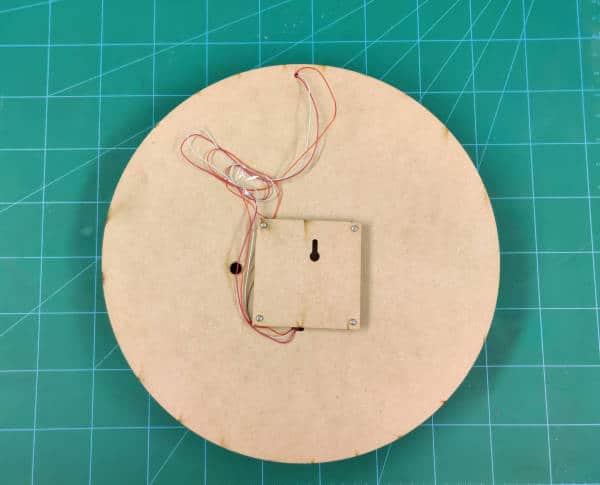
Now, fix these plates to evive through the base plate using M3 bolts of length 25mm length.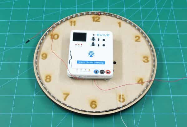
With this, our basic clock assembly is complete.
Advancing the Wall Clock
We can add as many functionalities as we want in our wall clock. As we have evive’s TFT Display we can display whatever we want. We will use the display to show the room’s temperature, humidity, time (24hrs format), and date. Thus, we will need the DHT11(Temperature and Humidity) sensor. Attach the sensor to evive as given in the next step.
With this, our entire assembly is completed.
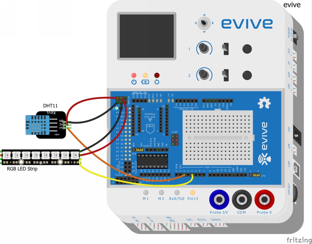
Making the Connections
Make the connections as given below:
- RGB Strip
- VCC: 5V of evive
- GND: GND of evive
- DIN: Digital Pin4 of evive
- DHT11:
- VCC: 5V of evive
- GND: GND of evive
- OUT: Digital Pin2 of evive
Look at the below fritzing image for the better understanding of the Circuit Diagram: icti
icti
Setting Time and Date
There is an inbuilt RTC in evive. But before using it, we need to initialize it. Follow the following steps:
Time:
To change the time slide the Slide switch 1 upwards.
- Potentiometer 1 to set the hour.
- Potentiometer 2 to set the minutes.
Date:
To change the date slide the Slide switch 1 downwards.
- Potentiometer 1 to set the date
- Potentiometer 2 to set the month
- Tactile switch 1 to increase the year count by 1
- Tactile switch 2 to decrease the year count by 1
Coding the Clock
We are going to code our clock in a simple way that is using PictoBlox– a graphical programming software. Either write the following script in PictoBlox or directly download and upload the code to evive from the code section:
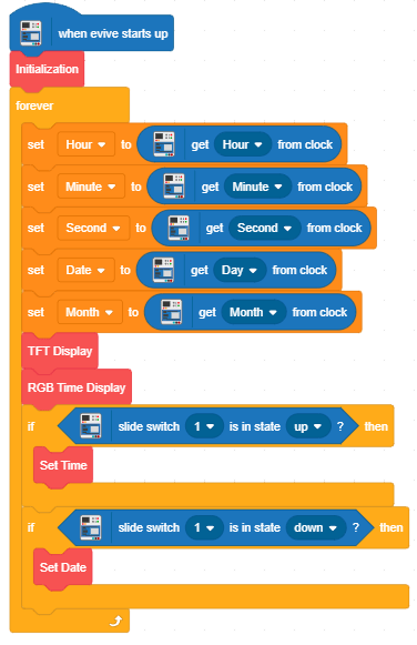
The first block is the initialization block, that initializes the RGB as well the TFT Display.
The below two blocks “Set Time” and “Set Date” are used to set the time and date in RTC which is found inbuilt in evive. We need to set the time and date using potentiometers and tactile switch of evive.
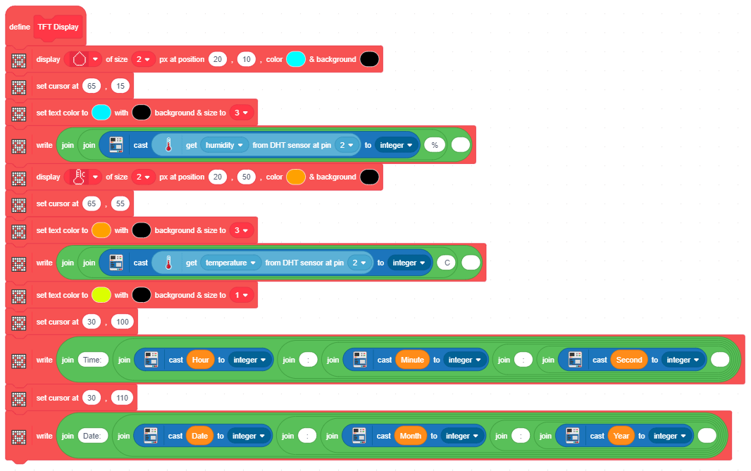
 This block is used to display Humidity and Temperature along with the symbols. The value of both temperature and humidity will be obtained from the DHT11 sensor. Also, we will display the time and data on the display.
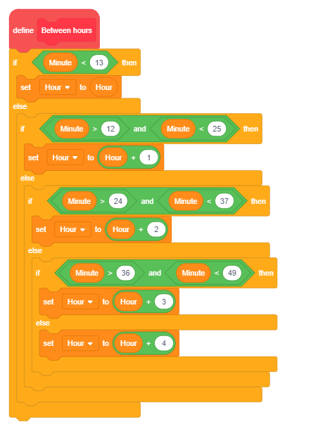
 This block is used to divide 60 minutes into 5 slots between two numbers.
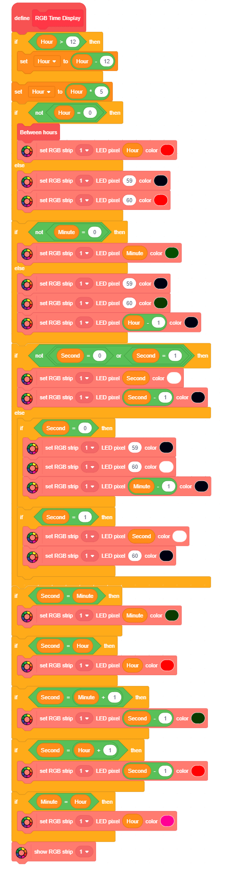
The main block, which will start the action and call the required blocks.
Conclusion
With this, your DIY RGB LED wall clock is all set to add the ultra-modern touch to your living room!


 _ Naga Pranav Patcha 3-39 screenshot")


